Alistair Potter's RC plane tips.
My Old Fogey fix; with improved handling and flight times.
Back to planes list. Back to homepage.
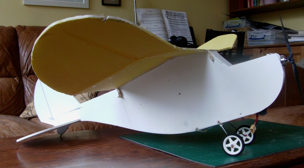
"Lazy Fogey"
Wingspan – 970 mm / 38.1 inches
Length - 750 mm / 29.5 inches
AUW - with a 3S 1000mah LiPo is 650 grams / 23 ozs. (Heavy foam board version.)
Drive - Blue Wonder 1200KV motor with a 9 x 3.8 prop.
Plans - PDF file. Fuselage only - Lazy Fogey
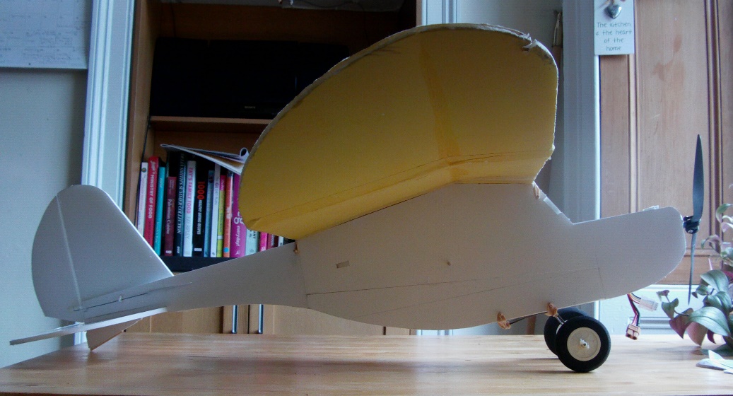
"Bush Fogey"
Wingspan – 970 mm / 38.1 inches
Length - 750 mm / 29.5 inches
AUW - with a 3S 1000mah LiPo is 620 grams / 23 ozs. (Heavy foam board version.)
Drive - Blue Wonder 1200KV motor with a 9 x 3.8 prop.
Plans - PDF file. Fuselage only - Bush Fogey
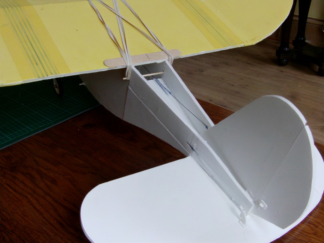
Above are two end results from my investigations. On both designs, the INSERT component is 'tabbed' to fit into holes that are cut into the fuselage sides and should be glued along its length. Do one side at a time. The INSERT stretches into the 'cabin' space to help reinforce the fold point in the fuselage, where it also becomes an ideal mounting point for the servos. This means the 'stock' servo mount is just used to support and align the power pod. The standard Old Fogey tail assembly slots into the INSERT; make sure it's square and level, and make any adjustments before gluing. (Makes sense when you open the plan.)
If you want to see how the planes above fly, look at the last 3 videos on this page.
Now, you could just download the plans and dash-off to build your hassle-free versions of an Old Fogey style plane that uses the Old Fogey wingset, but you could also read on to find out how these planes came about.
First off – the stock Dollar Tree Foam Board Old Fogey does exactly what it says on the box. As many will testify, it’s a fine light wind and indoor slow flyer. If you fly it within those limitations, you’ll have a very rewarding flying experience.
However, and I’ve watched plenty of YouTube videos to confirm this, a lot of pilots want to fly the Old Fogey in the wind conditions they experience most of the time (medium to strong, rather than light), and they want to fly it the way they want, which is usually a lot faster than intended! As you'll see in the first video, wing-waggle results from flying the Old Fogey at speeds that exceed its design limitations. This will be more obvious to us heavier foam builders, who often need to push our planes along a little faster, which brings us closer to the Old Fogey's 'wing-waggle zone' and only allows us a narrow speed range where the plane performs as it should.
So, is there a way to change the Old Fogey to achieve the goal of greater stability at speed without resorting to 'negative' inputs?
By negative inputs I mean any of these solutions;
1. A large down deflection on the elevator, just to make the plane fly level (which produces drag).
2. Increased nose weight to 'hold the nose down' (which can mean adding to the flying weight, and definitely means flying nose-heavy, which makes it hard to slow down on landing approaches).
3. Using an excessively steep motor thrust angle to combat the wing lift, (which just seems a nonsense, and a waste of battery power which could be better used to keep the plane in the air for longer).
When I tried to fly my heavy foam Old Fogey faster, I encountered the dreaded wing-waggle problem. Thinking (in error) that it was tail heavy, I relied on pushing the CG forward to ‘force’ the plane to fly level and true, but I eventually came up with a more drastic solution;
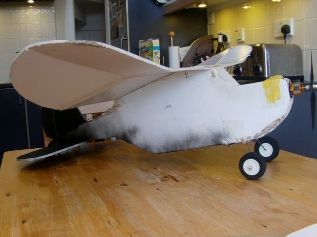
This 'surgically enhanced' Old Fogey went on to have an interesting life; appearing in classic videos like Blustery Old Fogey, Another Windy Day for the Old Fogey and in Wing Envy as a biplane. It flew fine, and at the time I was happy to have a plane that didn't wing-waggle.
Then I encountered the same Old Fogey ‘wing set’ being used in the Smash Drone, which I built in a modified form.
From the start I was never happy with how MY Smash Drone flew, and found I had to add a pile of nose weight to get it to fly level and true (sound familiar?). Even after adjusting the thrust angle of the motor, which helped, the plane still needed that extra nose weight. I eventually concluded that the plane was developing too much lift! This led me to the radical decision to reduce the wing’s Angle of Incidence, which, wonder-of-wonders, transformed the plane’s performance!
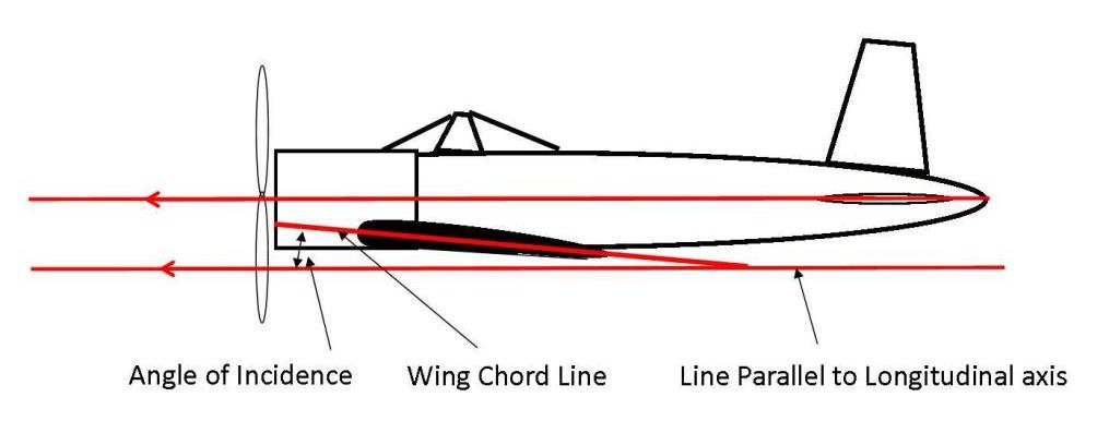
Angle of Incidence is the angle between the wing chord and the plane’s longitudinal axis (also, in most cases, a line parallel to the chord of the horizontal stabilizer).
At this point I must sing the praises of the ‘Old Fogey’ wing set – I’ve consistently found it’s capable of producing a humongous amount of lift.
As you can see from my experience with the Smash Drone and its later incarnation as a tractor plane and from my more recent proving and modification flights for the SE5 biplane I knew I could get a freer-flying model (and better performance) with a much smaller Angle of Incidence, which could even, due to more efficient aerodynamics, produce better slow flying performance and longer flight times.
This isn’t just me. If you follow this link, and go a little over halfway down the page you’ll see the whole Angle of Incidence and differential lift thing explained much better than I ever could. (If the image appears as a narrow strip down the left side of the new browser window, hover a mouse pointer over it and a magnifying glass with a plus in it will appear - click the mouse and the image will spread across the window.)
And another great source of Angle of Incidence
information and guidance for model planes can be found here;
Electric Plane by Gordon
Basically, on planes with a higher Angle of Incidence, the faster you go, the more
effective the main wing becomes relative to the horizontal stabiliser. This can
often be controlled by a small adjustment of the elevator or a little 'downward'
adjustment of the motor's thrust angle. However, in extreme
examples, these remedial measures are not enough and a lot of flyers mistake the
resulting 'nose up' tendency
as an indication that the plane is 'tail
heavy'. But it's not - just slow the plane down, the lift equalises, and the
plane starts to fly level again - no shift in CG required, just a slower passage
through the air.
The other factor with a high Angle of Incidence is drag. Yes, it's fine to play off drag against lift, but if you've already got a large enough wing area to allow the plane to fly slowly, I feel there's really nothing gained by making it harder for the plane to move forward through the air.
So that’s my initial logic for the Old Fogey; because the lift at higher speeds of the main wing is not proportionally matched by the horizontal stabiliser, the tail starts to droop, and as the tail droops it throws the plane into a ‘high alpha’ flight mode and the wing starts to behave like a leaf fluttering in the wind. (It's definitely not as simple as that, but it gave me a starting point.)
Armed with this knowledge, I decided to prove my case for reducing the ‘stock’ Angle of Incidence of the Old Fogey by building a new, modified version.
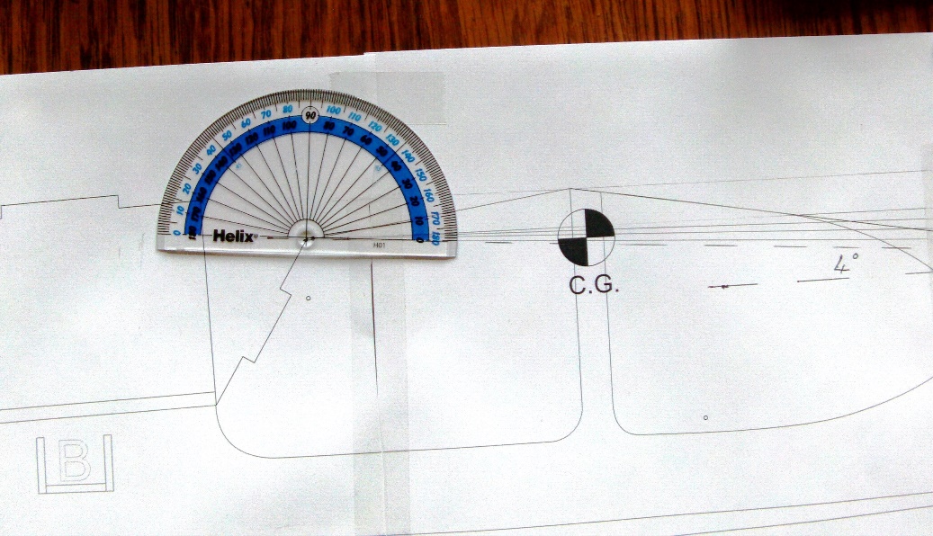
Checking my paper plans for the Old Fogey I found that, taken across the front
and back edges of the wing, it had an the Angle of Incidence of four degrees.
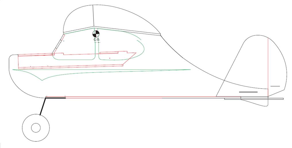
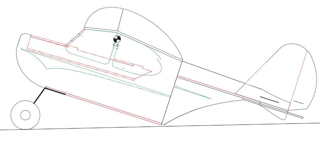
Here’s a mock-up of what I wanted to achieve. It doesn’t look too different, until you notice the ‘break’ in the cabin line at the back where I swung the wing up. I also added a new curve to tidy up the fuselage line that trails off to the tail assembly.
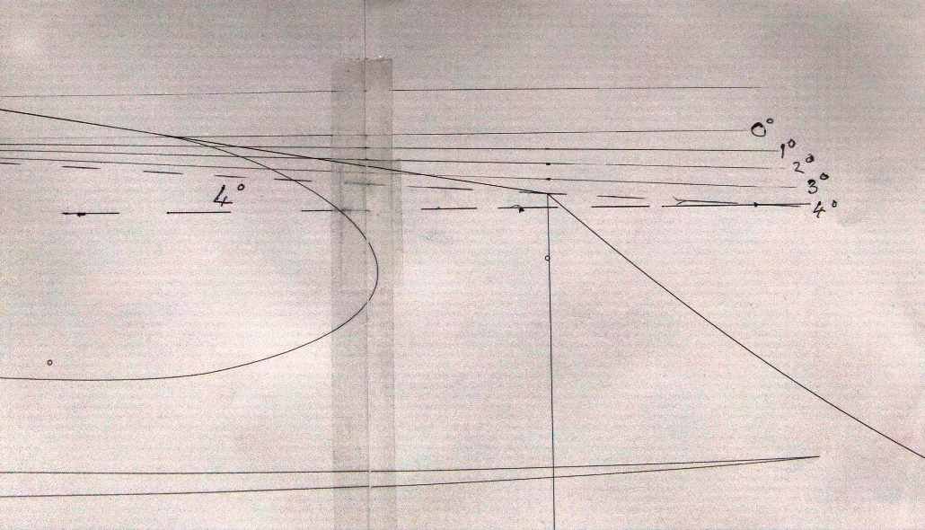
Next stage was to alter the actual plans. But how much to change it? I
simplified my choices; in one degree steps from the standard four degrees right
through to zero degrees.
A lot of flat-bottomed wing foam board planes fly with a zero Angle of Incidence, so I was tempted to go for the zero degree option...
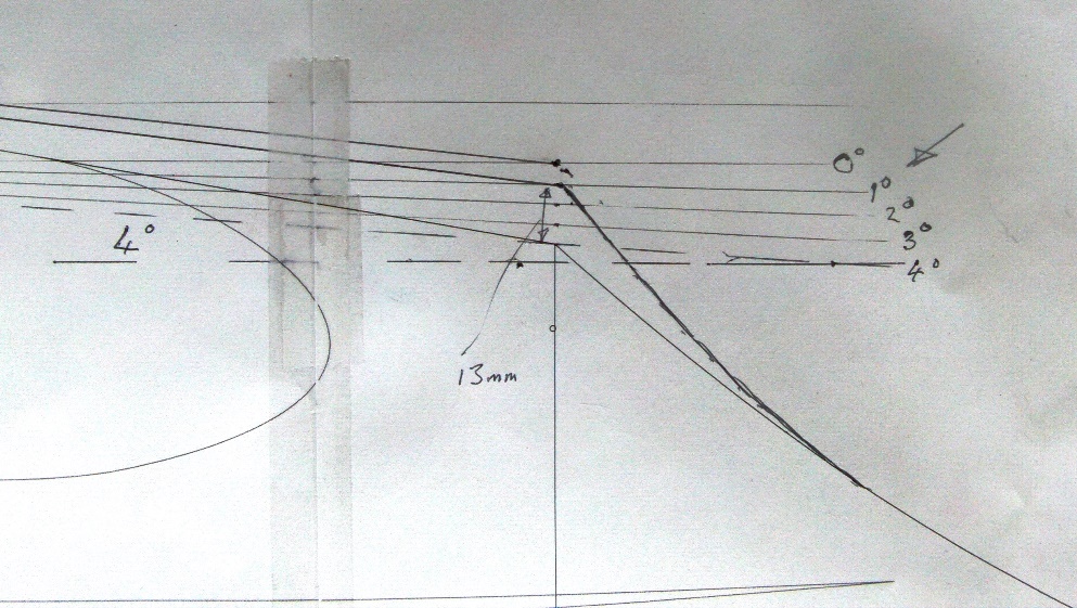
...but I ‘bottled out’ and decided to go with one degree, which, at the back of
the wing seat, handily coincides with a vertical measurement of 13mm above the
original position (a tiny bit less than ½”). After marking on the new profile, I
sketched-in a modified curve on the fuselage.
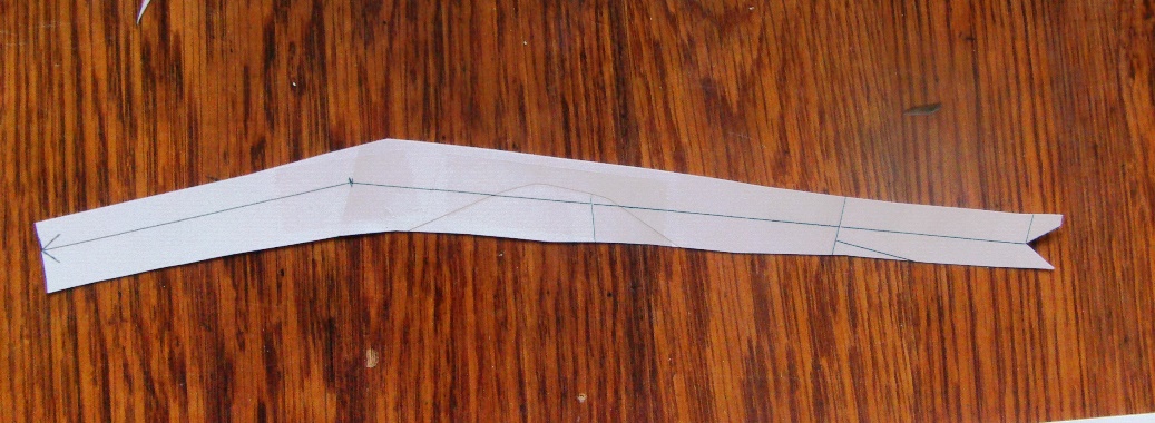
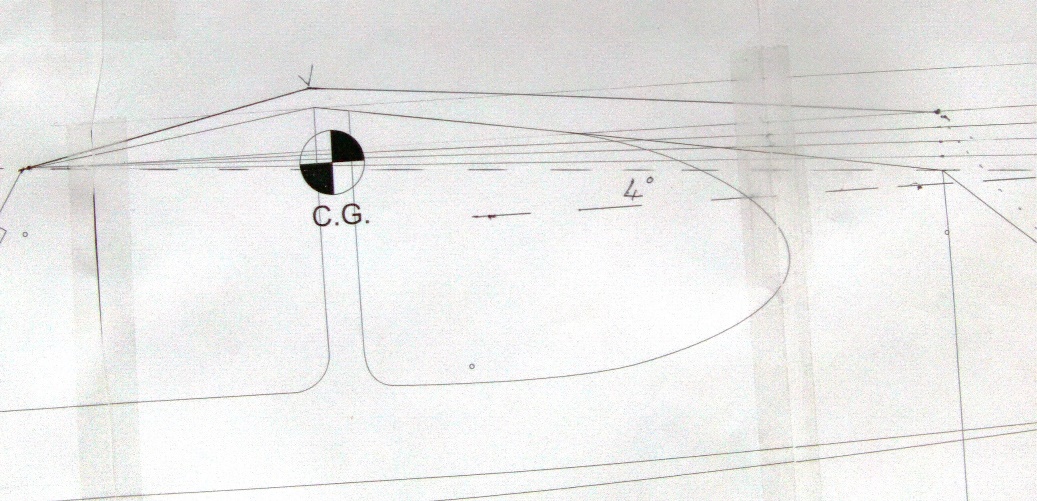
I used this little template to mark the wing apex and rear points. The front
(with the arrow) stays put and the template swings -about the front to get the
little ‘vee’ at the back to cross the correct line I’d already marked on the
paper. The wing apex was then marked by pushing a pin through the template.
I repeated the same exercise on the ‘other’ side of the plan by flipping the
template over – this time I included another little ‘vee’ nick to help locate
the wing apex.
After that it was the familiar process for us paper plan-to-foam board builders. I usually mark through the paper plan with a pin and then follow a dot-to-dot path to re-draw the cutting lines onto the board.
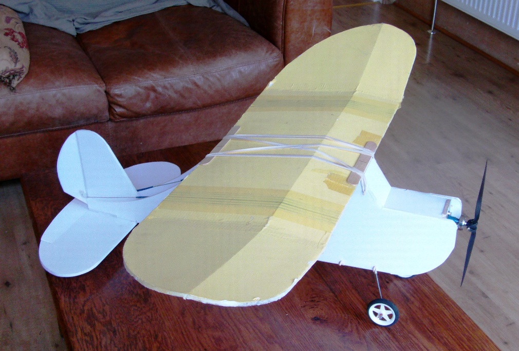
Fast forward and here it is, the ‘new’ Old Fogey, and yes... that IS the dodgy,
moth-eaten 3 year old wing from my very first Old Fogey.
Hard to spot the difference in the fuselage, but it’s there.
Now, the question you all want answered - did it make any difference? See for yourself;
OK, it’s a maiden, I start out too strong on the throttle and straight away the wing-waggle kicks in. But then I get the hang of it, ease off the throttle and it all settles down. Sadly, I haven’t managed to eliminate the wing-waggle, so I suppose I should hang my head in shame and admit defeat. But I am able to fly faster than I could previously, and I am flying on the correct CG instead of the super nose-heavy one adopted by many. It’s definitely a couple of small pluses, but it's also very disappointing.
I’ve flown these Old Fogey wing sets on three other planes; my original modified Old Fogey, the smash drone, and the Frankenplane I built from the Smash Drone. All of those flew very nicely, and the last two with a significantly reduced Angle of Incidence (and correct CG), and all with no bad tendencies. So what’s the deal, why didn’t it work this time? I could probably baffle myself and everyone else with a hodgepodge of aeronautical half truths and speculation, but maybe it's easier just to look at what I know from previous experience.
I had already ‘fixed’ wing-waggle on my first Old Fogey using the solution of lifting the tail assembly...

...which got rid of most of the problem, so I had a clue about what to try next. I will admit I had less understanding of the differential lift problem at the time and didn't think to reduce the Angle of Incidence as well. Meaning - I fell into the trap of thinking the plane was still tail heavy and flew it with a very nose heavy CG. (That's the pile of coins under the yellow tape!) Which also means I unwittingly lost the slow flying performance, which meant if I slowed down, the plane nose dived! Which again I assumed was because my plane was built from heavier foam board. Plus carrying extra nose weight meant carrying extra total weight... 860 grams / 30.4 ozs eventually. (Almost twice the flying weight of a DTFB Old Fogey.) I'm amazed the plane flew, but it did, and pretty well, all things considered. I digress... but it does show how that first error in thinking produced a whole pile of negative outcomes.
Anyway, to continue my investigation I decided to repeat that same fix on my ‘new’ low Angle of Incidence version of the plane. This time I did it without shortening the fuselage.
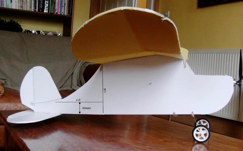
To start, I disconnected my rudder and elevator linkages and cut-off the whole tail along the line of the fold at the back of the wing. I marked the vertical cutting lines using a set-square pressed onto the bottom of the plane. That makes fixing the tail back on much easier, but if you get it slightly wrong it’s easy enough to sand a little off to get the tail sitting square. I also cut off most of the curving portions from the side panels. The cut to remove the the curved sections is parallel to the bottom of the box section and 40mm or 1 37/64" up from that bottom edge (sorry about the horrible imperial equivalent).
Of course, at this stage you need to remember my plane already has a modified wing seating. To reduce the Angle of Incidence you need to modify the standard wing seating, and it's best to do it now.
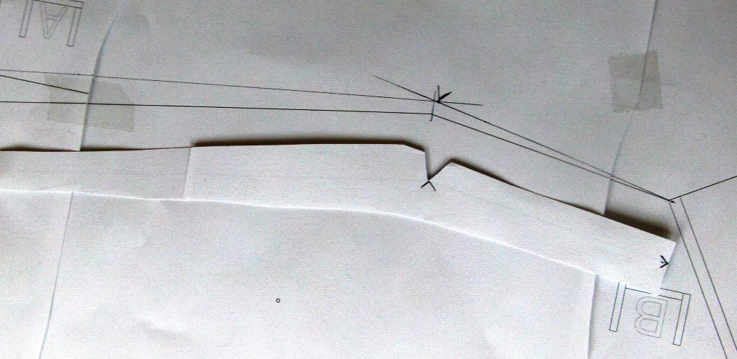
You can use this handy little template, which you can print out on A4 or letter size paper or card.
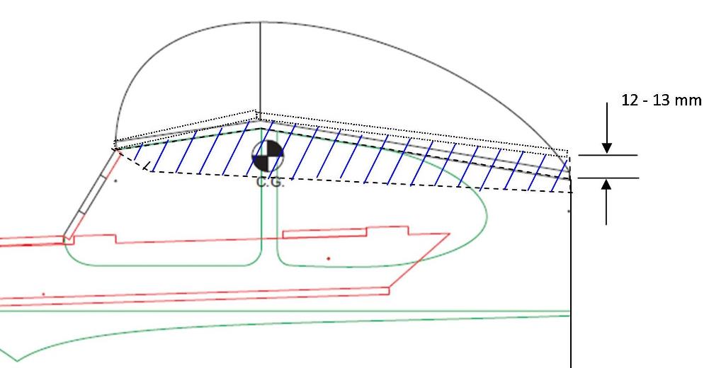
Transferred to foam board, the template will fill-in the space marked in blue, modifying the wing seat to the new one degree Angle of Incidence.
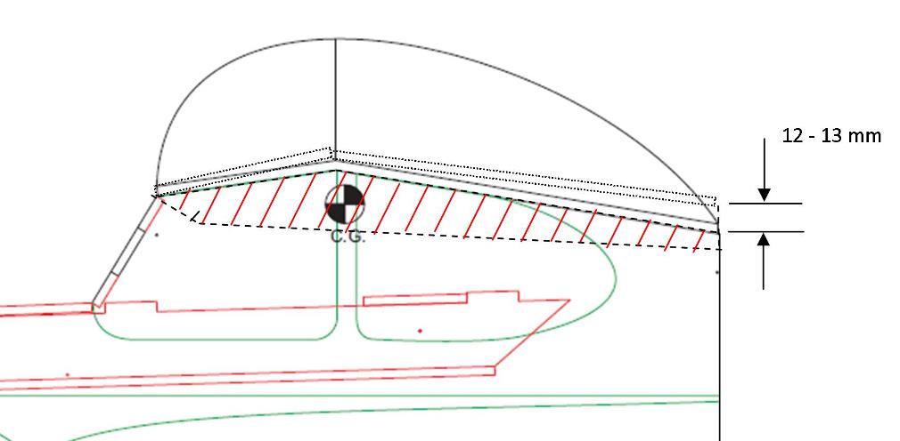
To work out what to remove, the template has the existing profile marked on it and this needs to be aligned with the existing seating to allow you to mark-on the cutting line. The piece that's going to be removed is the red hatched area shown above.
Only once you are totally happy with what needs to come off and what needs to go back on, then you can cut off the old profile and graft on the new bit.
Once that's done, the 'box' element of the tail assembly is glued back onto the fuselage, making sure it is square and level, and flush with the back edge of the wing seat. I flipped the off-cut curving portions and refitted them to the underside of the box, using them as fillets to help strengthen the tail. There was a little ‘fettling’ to fit them around the horizontal stabiliser, but nothing demanding.
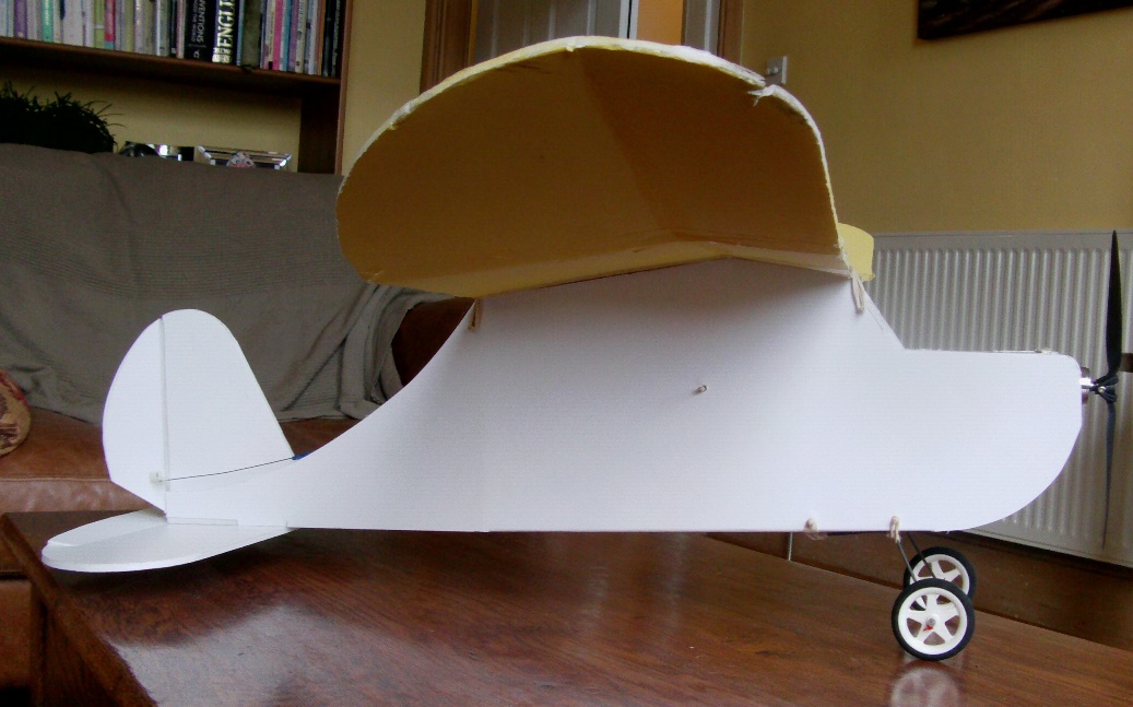
At that stage, I had a flat ‘cabin’ bottom running all the way back to the join. I’m sure it wouldn’t have mattered much, but it did look a bit ‘industrial’ (and kept the tail off the ground)...
...so I decided to modify the shape to what you see above. First I sketched-on a nice pair of linked curves on one side of the fuselage.
Then I slit the floor-to-side join, to free the floor up to the edge of my new curvy line. I then encouraged the floor to bend up enough to keep it out of the way for the first ‘curvy’ cut. Once I had that first curvy profile cut, I used the off-cut as a template to mark out the cutting line for the other side of the fuselage. After cutting the second side, I glued the floor section in place to stiffen the rear of the ‘cabin’.
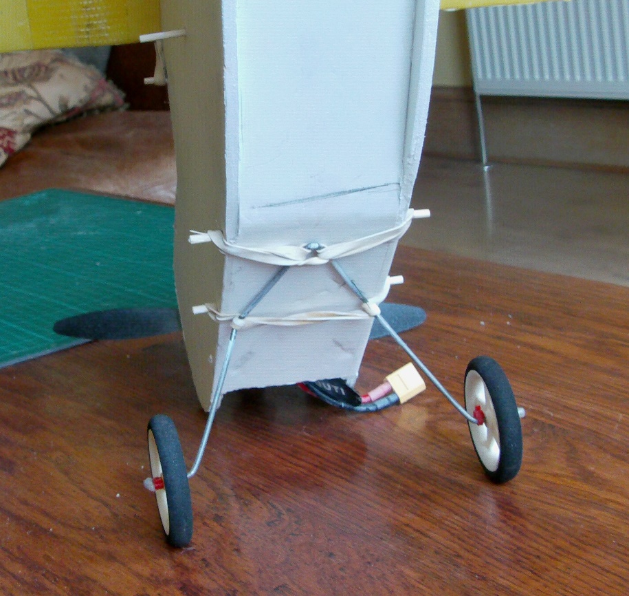
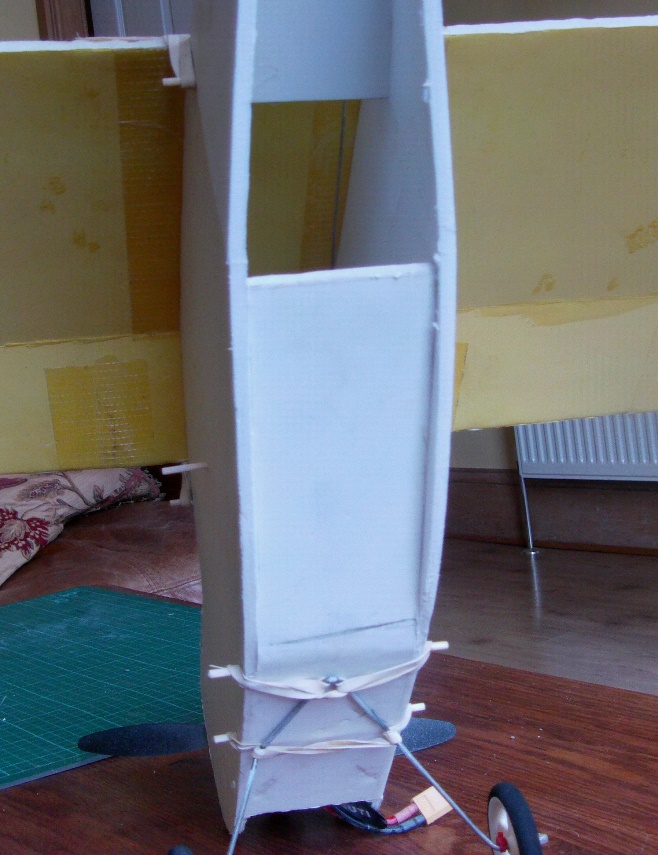
With my new ‘high tail’ I toyed with the idea of converting to a tricycle landing gear, but for simplicity I stuck with the tail dragger setup. After a little pondering I decided the plane would look a lot better with the wheels further back. I did this by moving the front skewer only and punching two new holes.
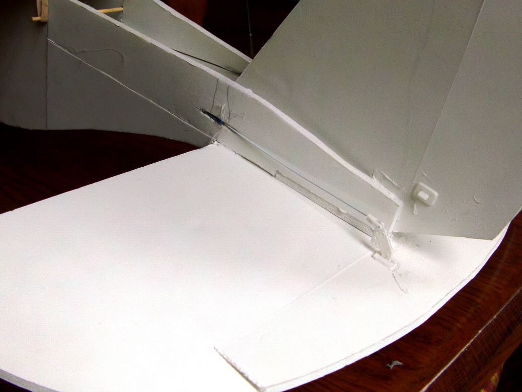
Control rods are led from exactly the same servo positions as before, but are fed through the fuselage at the back. I stuck a little length of tube (cotton bud stick) in the slit there to help control play in the wire.
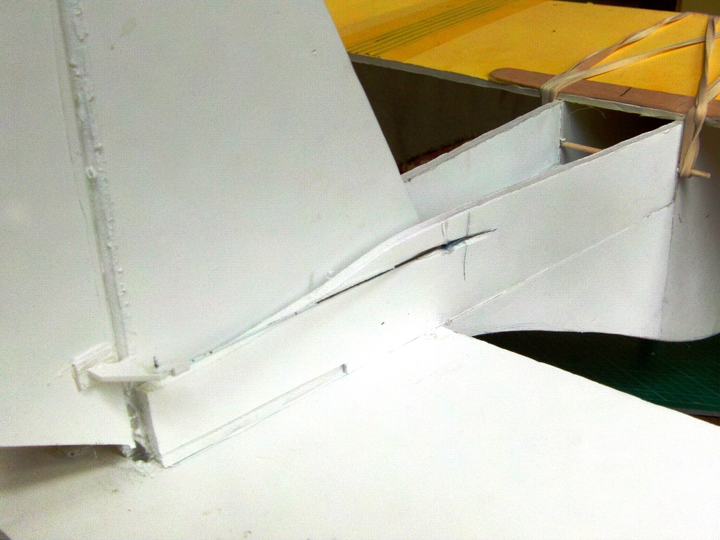
I did the same on the rudder side.
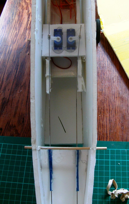
Inside, a couple of little tubes help direct the wire towards the servos. (An alternative would be to remount the servos where these two blue tubes are. That would shorten the control rods and reduce any play. On the correct CG I find this plane balances very easily with my 1000mah battery about a battery's length away from the front of the power pod, so there's plenty of room available at the front to re-adjust the balance for a slight change in the servo positions.)
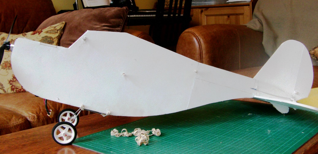
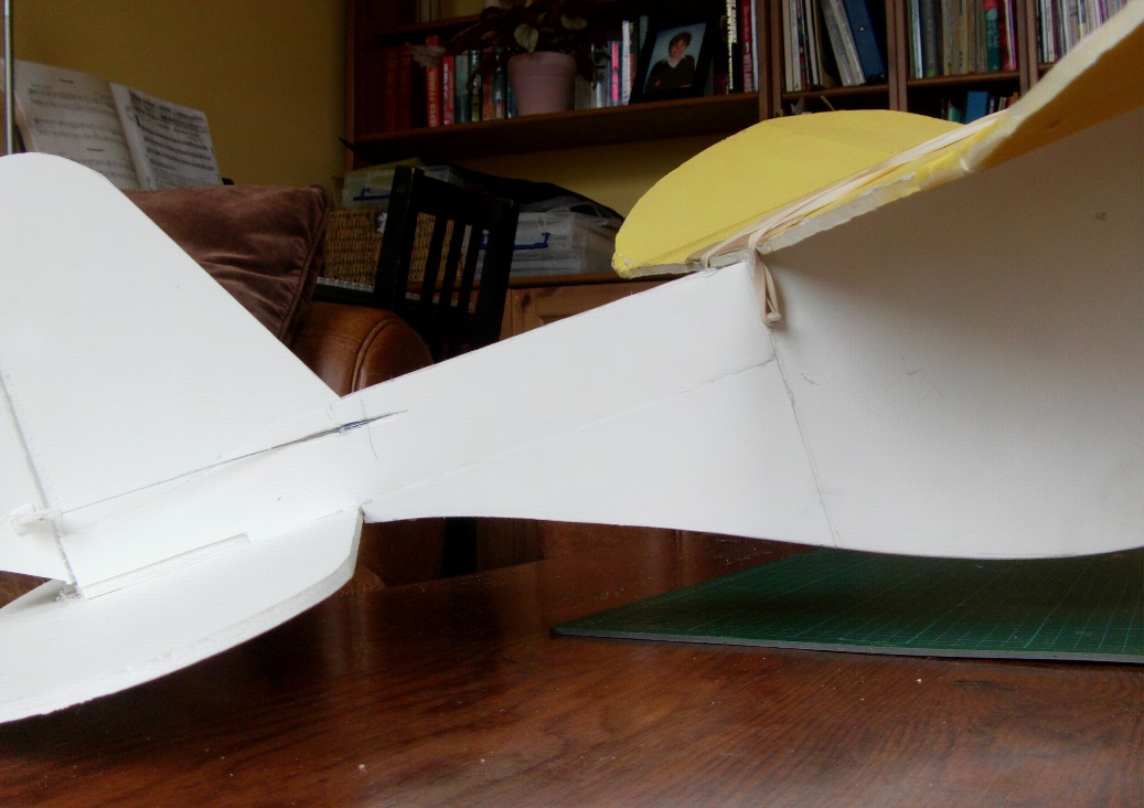
Without the wing, you can see how neat the top profile is, and how nicely the curves work...
...and here’s how the plane looks with the wing on.
So - new day, new plane, new video.
To make a fair comparison, I went with the ‘stock’ CG, just behind the wing apex fold. This is correct for the plans, and also agrees with the CG calculations I made using the calculator on this web page.
In my calculations I fudged some of the measurements, to allow for the wing curve, but it still produced the same result as the ‘official’ CG.
My All-Up-Weight with a 3S 1000mah LiPo is 650 grams / 23 ozs. This is heavier than a DTFB Old Fogey because I only have access to one of the heavier foam boards, but I’m still flying on a Blue Wonder 1200KV motor with a 9 x 3.8 prop. The motor runs a teeny bit hot with this prop - ideally I should use a slightly smaller prop, but I didn’t want an ‘anaemic’ power setup for the maiden.
Ignore the 'wobbles' in the first clip - I was trying to show how slow I could fly. It all makes sense once you see how easily the plane goes out from the first hand launch. By the end I hope you'll agree, the plane flies much, much better all round. Winds were about 4-5 mph, rising steadily as the day progressed. This is the result I was after. I’m flying on the correct CG, and I can fly ‘flat-out’ or slow with only very slight changes to the elevator trim, and no bad habits. I managed flight times of 10 minutes on a 1000mah LiPo, making the plane dramatically more flight efficient than my original Old Fogey.
When comparing slow speed performance, I feel it does very well considering its ‘heavy’ foam board construction. Without battery it weighs-in at 554 grams / 19.5 ozs. A ‘stock’ Old Fogey weighs-in at 377 grams / 13.3 ozs. Or with my 96 gram battery load; 650 grams v 475 grams. My version is about 25% heavier than the DTFB version! Someone would need to confirm this, but I'm pretty sure a modified DTFB version would fly almost as slowly as the original Old Fogey.
As far as I'm concerned, the new setup is a complete success.
This next video is another outing with wind speeds of 10-12 mph (which rose to about 15 mph by the end of the session). Definitely not Old Fogey weather, unless you hammer-on a whole pile of extra nose weight. My only compromise to the flying conditions was a small forward shift of the CG to the wing apex.
Even in these stronger winds, I managed flight times of around 8 ½ minutes on a 1000mah battery.
CONCLUSION
So - when is an Old Fogey not an Old Fogey? This version has the same fuselage length and wing set, but the tail assembly is lifted to bring it closer to the plane’s longitudinal axis. In addition, the Angle of Incidence of the wing is reduced from 4 to 1 degree. Taking all that into account, I suppose the answer is; it isn’t really an Old Fogey any more.
But if you have a donor Old Fogey sitting around, and you want to open-up its flying envelope, or are struggling to get it to ‘fly right’ for you, then I suggest that for a competent builder this is a fairly quick and easy modification of the existing airframe. One that will produce a more versatile and forgiving plane.
If you do go with the complete ‘mod’ package, make sure you use the ‘stock’ CG. Keeping this new plane super nose-heavy will just make it harder to slow down when landing, and deprive you of some great slow-flying performance.
If you want to build this plane from scratch, get a hold of the Flight Test plans for the wing, tail, power pod and servo mount. Then the choice is yours.
You can build the Lazy Fogey, which has a standard depth alternate fuselage.
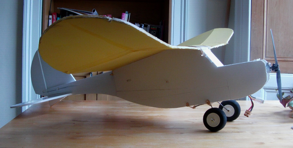
OR, how about the very sleek Bush Fogey, which has a shallower fuselage depth. Here's how it flies;