Alistair Potter's RC plane tips.
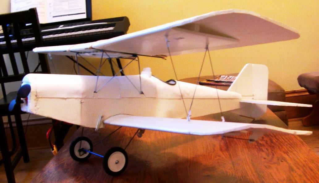
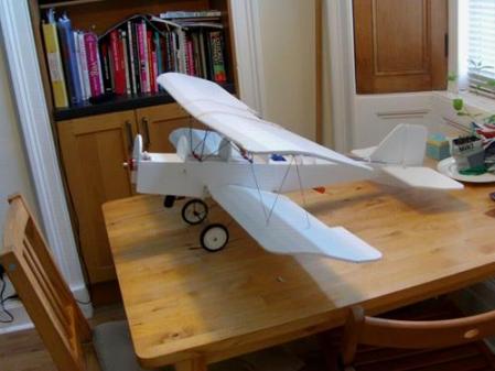
WW1 Royal Aircraft Factory SE5 biplane.
Back to planes list. Back to homepage.
This is my third design for a biplane using my wire cabane system with internal mounting rails. The system is holding–up well, coping with lots of landing knocks and a couple of reasonably firm crashes. One crash with my Polikarpov Po–2 knocked the top wing off the cabane frame. Repairs involved replacing the little foam centring plates on the top wing and repairing a torn skewer hole for the lower wing elastic. Zero damage to the cabane assembly!
UPDATE 12/07/16 The cabane system has performed so well, I've decided to simplify it. I'll keep the side rail and saddle version for the Polikarpov Po2/U2, and any other builds that have the cabane elements very close to the nose of the plane, but for those with cabanes further back on the fuselage, a deck-mounted assembly seems to do the job well enough. I've also remodelled the SE5 to make the nose and forward turtle deck closer to the earlier models, which is actually more streamlined. I've called it my "Version 2" and have modified the plans to include these changes.
This build is with one of the heavier foam boards. Built with one of the lighter boards I'm confident the flying weight could come down to just under 900 grams. This would produce an even slower flying model for a more scale appearance in the air. Of course there's a lot of 'scale' detail missing from my model, but the more detail you add, the heavier the plane is.
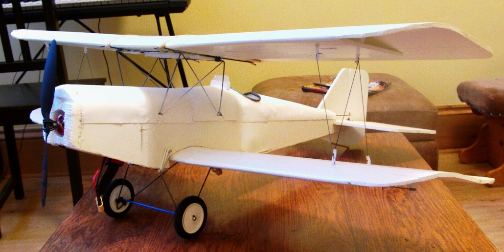
Wingspan – 940mm 37 inches.
Length – 740mm 29 inches.
AUW – 1120 grams with a 2200mah LiPo.
Drive – Emax CF2215 1200kv with a 9 x 3.8 SF prop.
Ver.2 Plans; SE5 & Small component set.
To whet your appetite, here's the maiden flight;
Preparation for the maiden involved a couple of clicks of right rudder and a click or two of right aileron. I started off VERY nose heavy AND with a little down elevator. From a hand launch the plane went out nicely, and flew fine after a little trimming out. After the flight I found I'd near–enough centred the rudder. My only thoughts were I felt it was a bit 'draggy' at times with a lot of motor action and not much speed increase.
I had designed–in a fair bit of wing incidence, 2.5 degrees, and I think I was creating too much lift. In essence the extra nose weight was balancing–out the extra lift – this was very noticeable on the run–in for the landing where I found it hard to lift the nose and slow the plane down.
I took the plane home and made the Angle of Incidence shallower, reducing it from 2.5 degrees to 1.5 degrees. What a difference that made! Here's the plane flying after the changes, and with the CG shifted back;
It was never my intention, but when I finished I discovered the plane's length and wingspan were almost identical to the Parkzone SE5a that was popular a few years ago. Out of interest I checked the Parkzone's flying weight. The figure quoted is 1150 grams with an 1800mah LiPo. My plane is 1120 grams with a 2200mah LiPo, so it's already lighter for a larger battery capacity. My build is with one of the heavier foam boards, and I think that if it were built with one of the lighter boards the flying weight could come down to under 900 grams. This would produce an even slower flying model for a more scale appearance in the air.
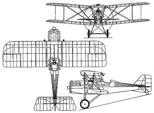
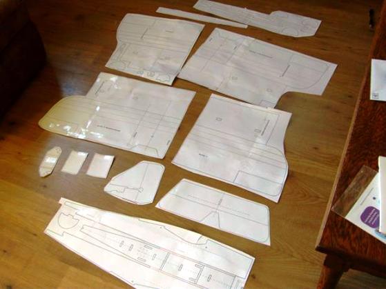
It all starts with a 3–view, which I was able to find on the internet. This detail was converted into components using Nerdnic's 'tracing' method and Adobe InDesign software – a Photoshop–type desktop publishing package that uses layering. My A1 'document' workspace is the same as my foam board sheet, which allowed me to scale and fit the components to the sheet. This plane can be built from 2 sheets of A1 foam board.
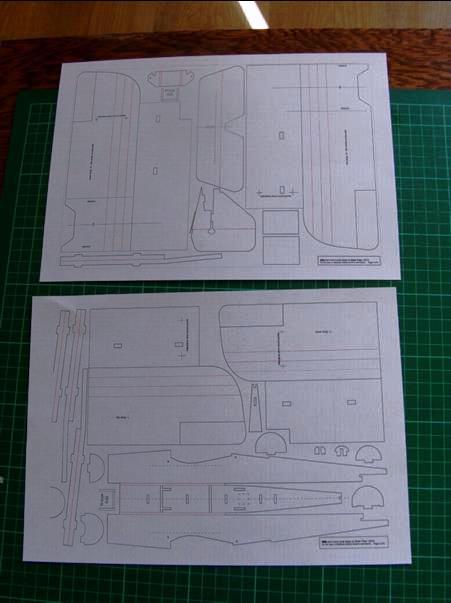
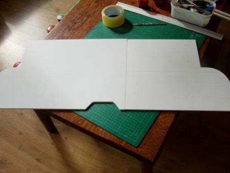
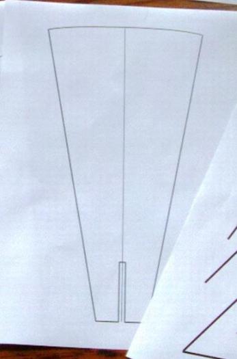
Here's how it all fits on the two sheets, though these are just A4 'mini' versions to help me place my templates on the foam board. (Some of the component detail has changed since this picture, but it all still fits on two sheets.)
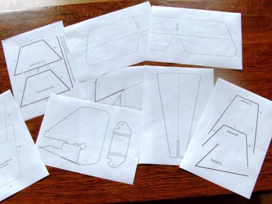
I've also included a 'small component' set of drawings which will print on A4 or letter size paper. This will save a bit of stitching, and the set also includes the wire bending guides and the side view of the cabane geometry.
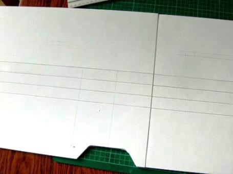
After tiled printing the larger components are stitched together with clear tape and then the detail transferred to the foam board. I use a pin to prick through the paper plan into the foam board and then redrew the components on the foam. I also took advantage of any straight edges on the foam board to reduce the number of cuts. The layout scheme in the PDF plans is designed for printing to A1 paper or foam board, so there's a little 'white space' around each item and around the edge of the plan, but if you're transferring the detail from plan to foam board by hand there's no reason to leave empty space around each component – especially if there's a handy straight edge or right angle corner that can save you a long cut.
The build uses many of the basic techniques illustrated in the Flite Test videos. I don't mention every stage, as I assume you'll be familiar with most of those techniques and a competent foam–board–builder before attempting this model. However if there's something obvious I've missed, not explained clearly or you need a little more info, please get in touch and I'll try to sort it out.
Fuselage.
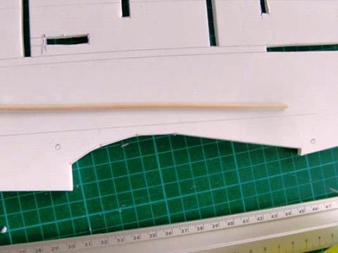
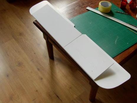
Cut the fuselage outline and all the slots etc. (At this stage I adjusted the locating slots for my custom (short) power pod.) I will update this build sequence, but if you look at the new plans you'll find these embedded skewers are no longer used.
(Just pretend that skewer isn't there!) Ready to fold–up the box fuselage, so the first stage is to remove the foam from the corners. This is a B–type fold so check what that means before gluing.
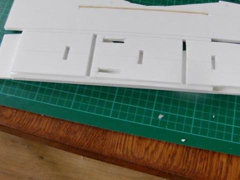
This B–type fold places the shaped tail deck section between the sides – NOT on top of them.
Each fuselage side is then glued to the tail deck, which produces a gentle curve and taper towards the tail. This can be done one side at a time. Take care not to twist or skew the sides – keep them perfectly aligned side–by side.
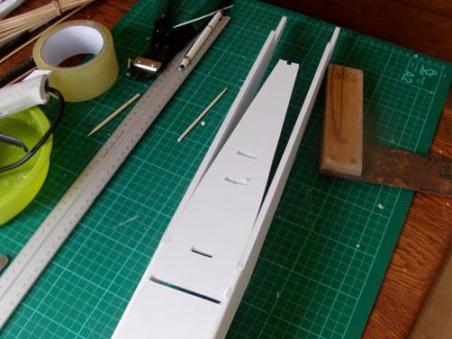
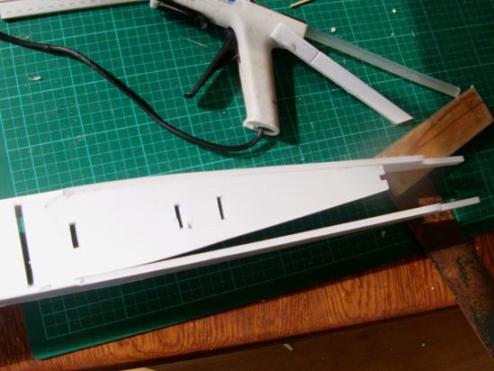
Next the tail assembly. Here's the horizontal stabiliser (HS). Because it's a large span I added a reinforcing skewer. Cut the paper and score with the skewer to open the slot.
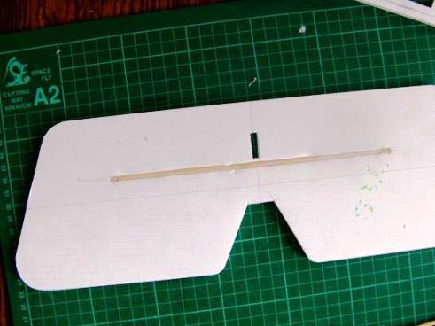
Skewer glued in place – keep the stabiliser flat until the glue is completely set.
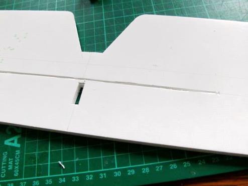
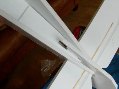
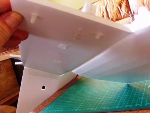
The horizontal and vertical stabilisers notch together in a very familiar manner to Flite Test and other similar builds. Here's a dry fit with the last full turtle deck former in place. Check and if necessary adjust the depth of those little slots in the fuselage sides (where the front edge of the HS locates) to get the HS square with the centreline of the fuselage.
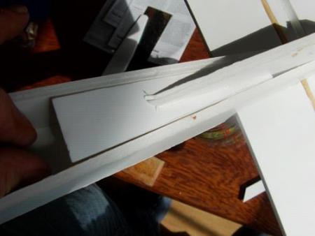
Still a dry fit. View from below showing a test fit of the fuselage insert that helps support the VS keel. This keel is also the mount for the tail skid. I left these components in place and moved–on to other fuselage components.
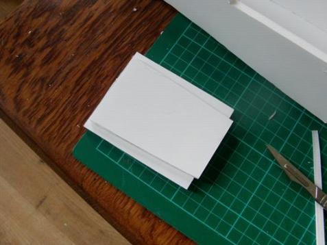
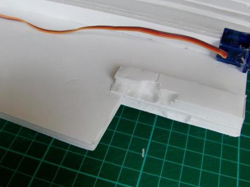
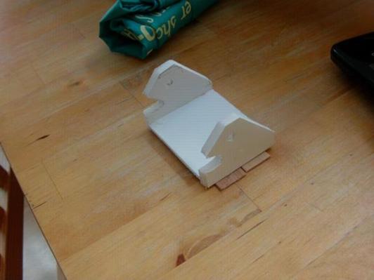
This is a pair of plates that sit behind the bottom wing and stiffen the centre of the fuselage. The inner plate has already been cut to match the inside of the fuselage profile. The outer plate can be cut to the outline in the plan, or can be trimmed to fit once it is glued in place.
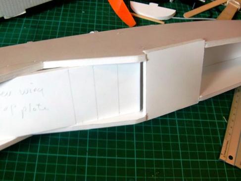
I missed a picture here, so this is actually a picture from my Polikarpov Po – 2 build, showing how you can use the lower wing centring plate to set the width of the fuselage before gluing the stiffening plates in place.
Here they are again on the SE5, glued in place. In this test build mine were slightly oversize, so I had to trim the front edges to fit neatly against the back of the wing, and of course I trimmed the sides flush with the fuselage.
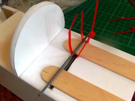
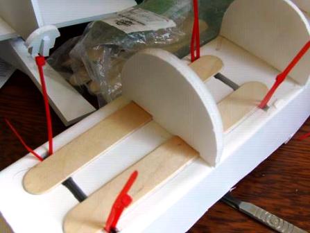
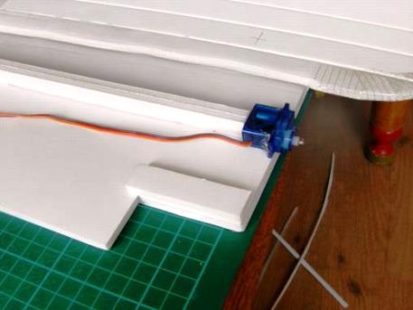
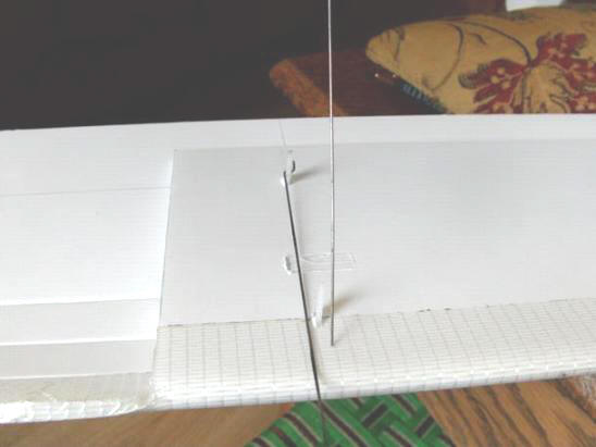
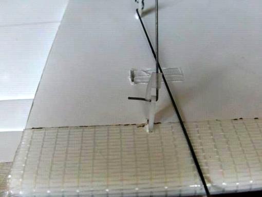
I'm missing proper pictures for this next bit, but get hold of a couple of used plastic 'gift cards' (Ikea family membership cards, Itunes card etc. etc.) Cut these to fit beneath the box fuselage deck, and stick them in place beneath where the cabane wires will go. This is an old picture, so ignoring the wire and embedded skewers, the card should be fitted as shown - one for each cabane mounting point. They just need held in place, so double sided adhesive tape (carpet tape?) would work as well as anything else.
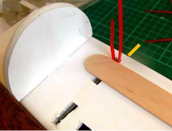
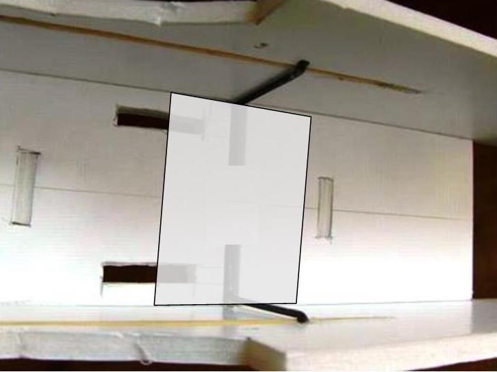
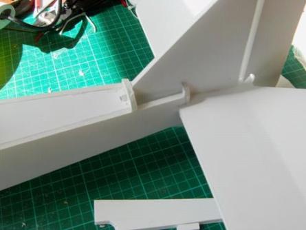
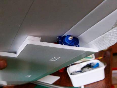
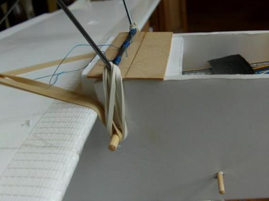
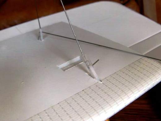
Sorry again, this is a mock-up of the assembly. A nice thick skewer is pushed through the fuselage beneath the cabane mounting point, keeping it nice and tight to the gift card reinforcing panel. Holes are then made in the card to allow a zip tie to pass from the top of the deck around the skewer and back up again. Once the top reinforcing (tongue depressor/lollipop stick) is in place, you now have a strong mounting point for the cabane frame, that wont crush the foam when the zip-tie is tightened.
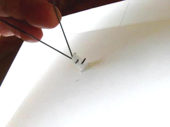
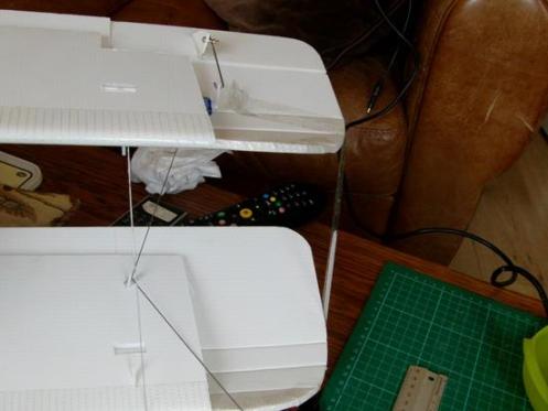
Demo time! The cabane assembly (illustrated by the top piece of wire) sits on top of the tongue depressors, all held down by the zip–ties that wrap around the skewer below. (Ok the picture isn't quite right, but you get the idea.)
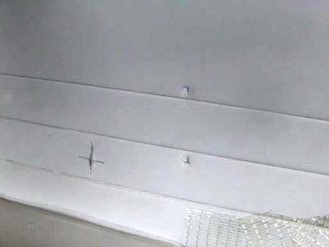
Mark the positions of the tongue depressors, making sure there's enough space at the sides for the zip–ties, and then glue them down.
Fit the turtle deck formers. You may need to do a little extra trimming on the one that goes over the tongue depressors.
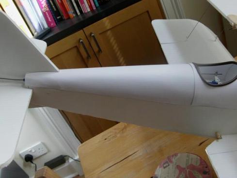
Fuselage starting to take shape. The two closely–spaced formers at the back will help support a headrest, if you fit one, but they are also there because the fuselage has a bit more curve at that point and the paper turtle deck cover could distort if not adequately supported. Note that I've still not fitted the front turtle deck former. Leave this off until you fit the power pod mounts.
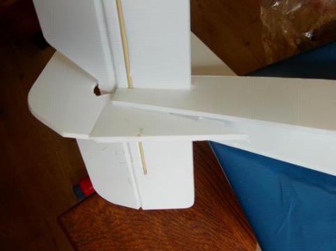
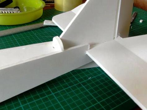
Time to fit the tail. Glue the HS and VS together first, making sure they are square and that there's full movement in the control surfaces. Next, glue the assembly into the tail, concentrating on getting it square to the fuselage and with good contact between the fuselage and the underside of the HS. The two little joins at the back between the VS and the fuselage sides can be glued after the first join has set by gently opening the sides and squeezing–in a little glue.
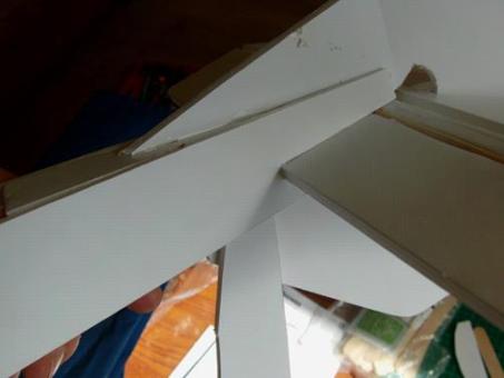
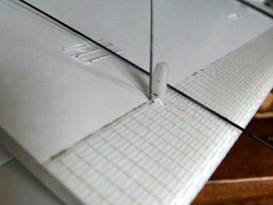
The little notch in the fuselage deck helps with keeping the tail aligned.
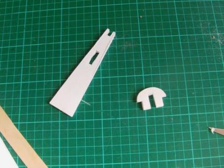
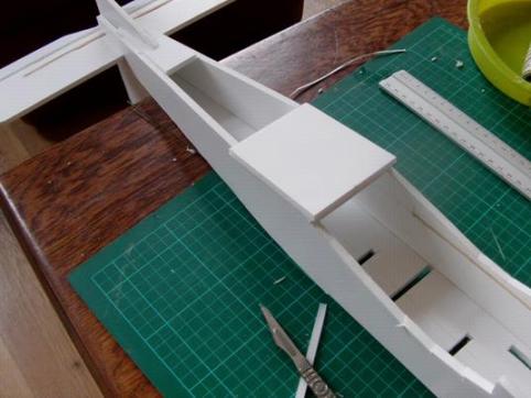
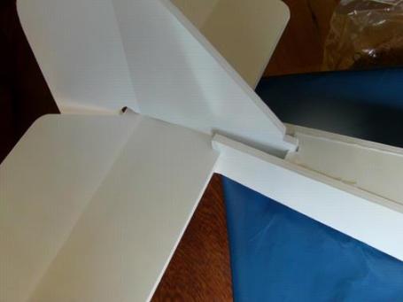
Now fit these two components. I needed to do a little sanding and shaping to get them to slide–in easily. Don't force them, they're just foam board.
The bottom component slides–in under the tailskid/keel. Once you can get it in place without any fuss, glue it to the keel. Don't worry about gluing it to the fuselage sides yet.
Glued in place (but not to the sides yet).
NOW you can spring the fuselage sides open and get some glue in. Do it one side at a time to make life a little easier.
Now glue the turtle deck former in place in front of the tail. Then add the two little 'left and right' turtle deck formers that go at the end of the fuselage either side of the VS. NOW is a good time to fit your power pod mounts and the last turtle deck former at the front.
Wings.
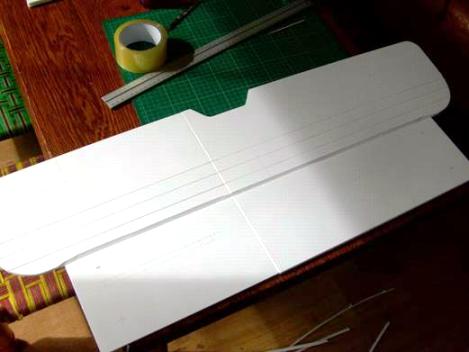
Time to build the wings. Top one first. Tape the two 'handed' sides together, but do not glue them together. Important – DO NOT cut the spar fitting slots yet!
This should be very familiar. Make a deep cut at the leading edge fold, and break the paper for the 'wing curve' bends.
Bend back the leading edge and cut the bevels on both sides.
Ready for folding and shaping.
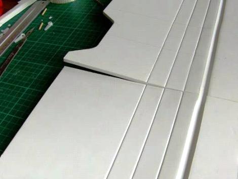
Bend and shape the whole wing as a single unit to establish a uniform shape, then partially cut the tape holding the wing sections together to free the top panel only! Keep the bottom panel taped join intact.
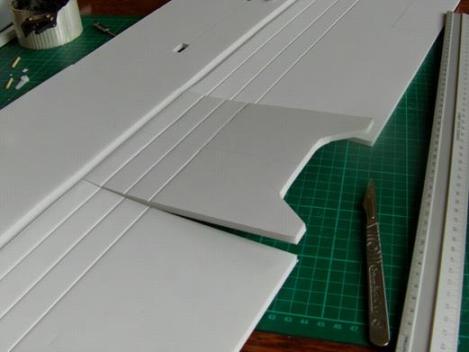
On the larger wing panel cut the foam board along the line of the dihedral to free the other side of the centre section.
Score and bend the dihedral turn. THIS is the best time to test fit the spar and cut the locating slots. So let's get that spar made.
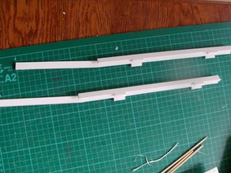
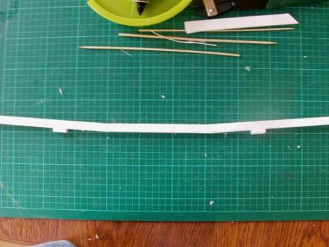
Here's the two sides L & R ready to join. I've actually modified this assembly, which will make it much easier to assemble, and also more stable. Having the joins on the turning points for the dihedral was not a good idea and resulted in some of the dihedral being lost as I folded the wing up.
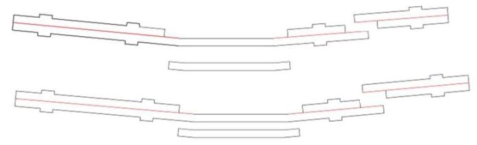
The new 3–piece spar design puts the joins well away from the dihedral turns, making the spar more stable and also allows easier fitting of the wire reinforcing if you decide to add it. If you've got plenty of foam board, you can also just make each spar up as a 2–piece unit; spar + central insert. My aim was to get the components on two sheets.
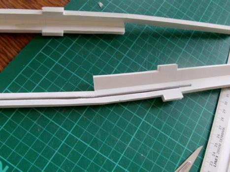
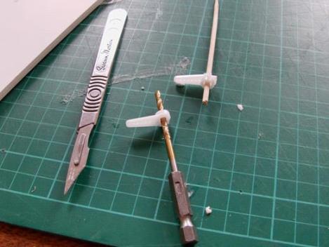
As mentioned, I like to reinforce my spars with a wire insert spanning the centre section. (300 long and 2.3mm diameter is about right.) The wire is first bent to follow the dihedral bends. A bit fiddly with this design, but the wire is then embedded in a cut slot in one side before the spar is folded over, trapping the wire inside. It's a bit like adding steel reinforcing to concrete.
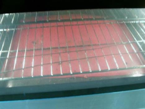
Run a pencil along the side of the wire at half the depth of the spar. Follow the line, cutting the paper, and then run the end of the wire along the cut. Create a deep–enough slot so that the wire will fit flush with the top of the paper. Before gluing the wire in place, a little pre–heating of the wire in an oven at its minimum setting – about 40 degrees C (not so hot you can't pick it up) will stop the 'cold' wire from setting the hot glue too quickly.
A quick and fiddly few minutes later, and the spar is assembled.
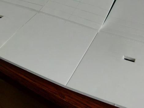
On this build I test–fitted and cut the spar locating slots in the wing earlier, by rocking the spar from side to side. This was NOT the best time or method for doing this and probably contributed to me losing some of the dihedral. Leave cutting the locating slots until NOW, when the wing can be properly bent into its dihedral form.
When the spar is ready to install, start by gluing it to the centre. Once it's set, work out a packing scheme to lift and tilt the small centre panel enough to get the right wing panel to sit flat on your work surface. Once you can establish this angle easily, run glue under the spar on this right–hand wing section only and press the spar and wing onto the flat, making sure your spacers maintain the dihedral to the centre section. Once it's set you can repeat the sequence for the left hand side using the same packing pieces to reproduce the dihedral angle – this time remember to run glue into the taped join as well.
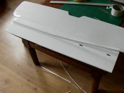
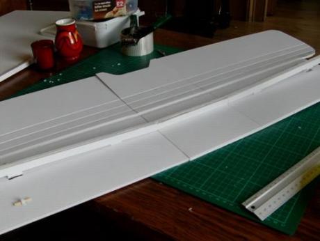
Now we're ready to fold–up the wing. Start with the centre panel. I glued the leading edge join, the spar and the trailing edge join. You can add glue to the curve folds if you want, but with this heavier foam board it seems less critical.
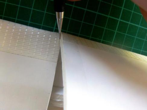
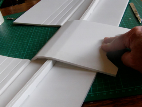
Fitting the wing top panels; keeping the centre section flat on the table prop each side of the wing to make sure the dihedrals are maintained and that they are the same for both sides. Trim one side at a time; fold the top panel over a little at first and mark the material to be trimmed away.
Unfold the panel and trim that first bit away before folding the panel over again. It will fold a little further this time and should start to slot–in neatly against the centre section. Mark on the next section to be trimmed, fold back and trim this away. Keep folding, marking and trimming for a good fit across the whole join. This is not a constant–width cut. It is widest at the fattest part of the wing and tapers away almost to nothing at the leading and trailing edges. Repeat for the other side.
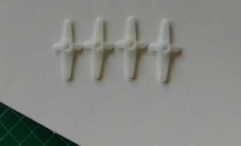
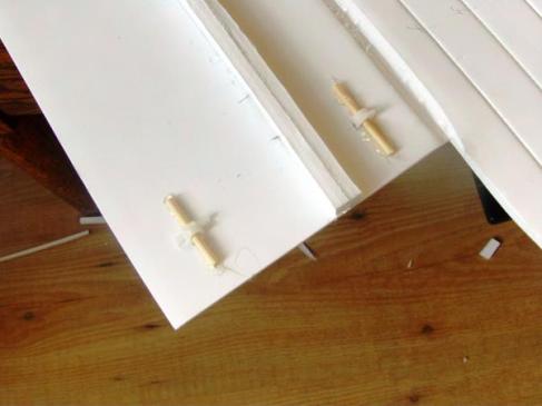
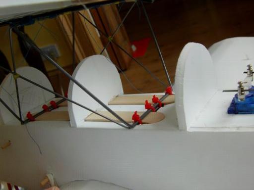
Last job before gluing–up is to fit the interplane strut mounts. You'll need some spare servo arms to make–up the mounts. I had these in my box; too many arms, but no problem – I'll just chop–off the bits I don't need, leaving just the centre and the longest arm.
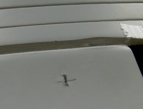
Cut slots to fit at the points shown on the plans. This is the top wing, so the mounts go through the bottom panel.
Prepare short lengths of skewer to fit through the servo arms.
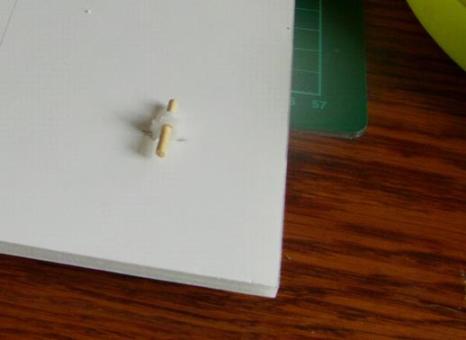
A dry–fit to show how it sits. Give them a bit of a push and wiggle to get the skewer to sit flush with the paper.
Angle the front mount backwards and the back mount goes straight up and down.
Here they are glued in place. Now you can fold–up the wing – take care to hang the projecting interplane strut mounts off the edge of your bench to allow you to get sufficient pressure on the top of the wing for good all–round contact. Finish the centre joins with a glue smear and tape.
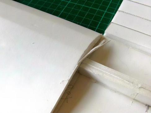
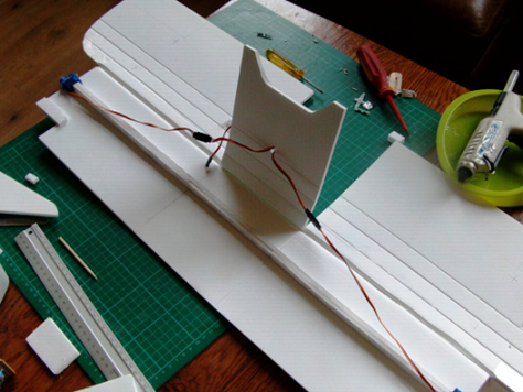
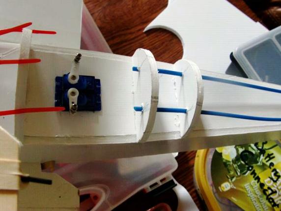
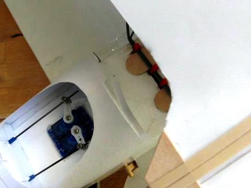
The lower wing is a repeat of the same procedure up until you are ready to glue the centre section. This wing needs a couple of extra components; there's a little wing spacer at the edge of the cut–out that gives clearance for the ailerons to move and there's the aileron servos. As you can see the servos are simply glued down at the end of the spar.
A test fold shows the corners of the servo hitting the top panel.
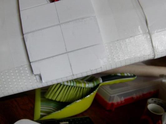
Where the servo has left dent marks in the panel dent them a little more to make sure the wing will fold over without any problems. Now fit the interplane strut mounts (servo arms and skewers) through the top of the wing. This time both the front and back mounts are angled a little towards the middle of the wing. Now try closing the wing again.
You'll find the back strut mount interferes with the wing spacer. Look at the impression it makes and keep trimming away material until you get the wing to close.
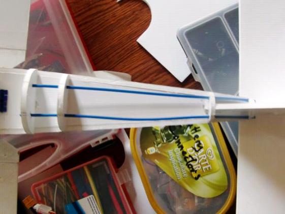
Here's what it looks like with the wing closed.
Extend your servo leads or join them with a Y–lead and pass the ends/end through a hole in the top of the wing. The top panels can now be closed over. Repeat the sequence for the top wing. Glue the centre first, cut the fitted joins to the centre section and then glue down the sides. It's easier this time because there's nothing sticking out of the bottom of the wing, but remember to pack the wing exactly the same as before to establish and maintain the same dihedral.
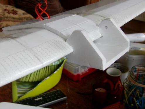
The bottom wing sits into the shaped recess in the fuselage and the wing centring pad glued on the top keeps it aligned. When gluing this pad to the wing take care to get it square and central as this controls the final alignment of the bottom wing. This pad also needs a little hole in it to allow the Y–lead to emerge. One extra detail is the undercarriage mount, shown here, which locates on the end of the wing.
To get it to fit, I had to notch out a pair of little recesses in the wing centring panel. This detail is now included in the plans, but may need a little more adjustment depending on build variations.
Undercarriage.
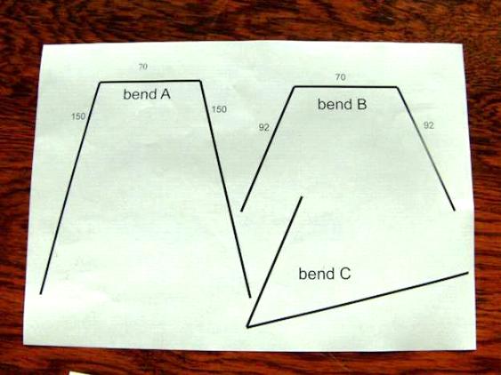
The info's all there on the plans.
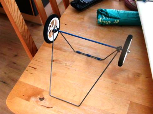
I was fortunate to have a long–enough wire to bend up the undercarriage in one piece, with a single overlapping threaded join. Just as easily, it can be made from two symmetrical sides with two overlapping joins. Follow the bending guides to make–up the frame and bind the overlapping join with thread and thin CA. Let the CA soak well in to the thread before using kicker to set the glue. The axle and wheels are held in place by twisted prop savers, which also give a little suspension. I've been using control rod snake to make an axle sleeve. This keeps the wheel spacing, making it less likely they will rub against the frame. You could also stick a few washers between the wheel and the frame. I find the spare prop inserts that come with a prop to fit it to different prop shaft diameters make good washers.
Finally, it all depends on this little component.
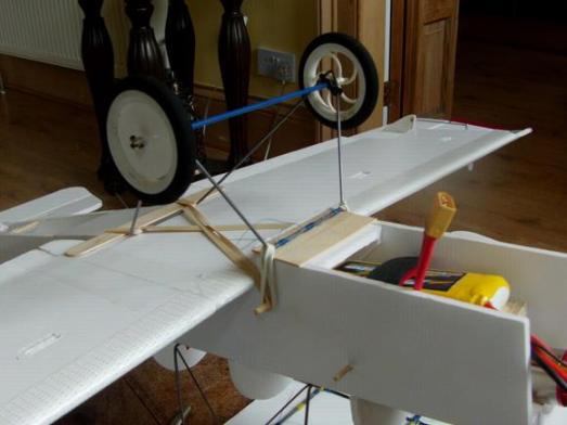
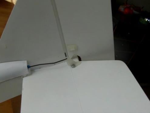
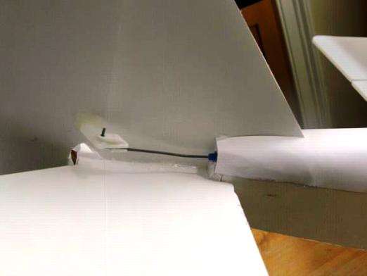
Here it is in place. The undercarriage mount is kept in place by its connection to the wing, and by the wing mounting skewer which passes through it. It makes a solid and stable platform for the front bar of the undercarriage to rest against.
Here's a close–up of how it's held on. I like these flexible systems. Stiff enough for take–offs and landings but unlikely to cause damage in a hard landing or crash. The top of the mount is protected with strips of tongue depressor – make them wide enough to overlap the fuselage sides as they also protect the edge of the fuselage.
Because the front is so secure, all the back needs are a couple of loops of the wing elastic. This should do the job, though it also needs another strip of tongue depressor beneath the wire to prevent damage to the underside of the wing.
Cabanes.
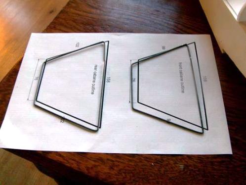
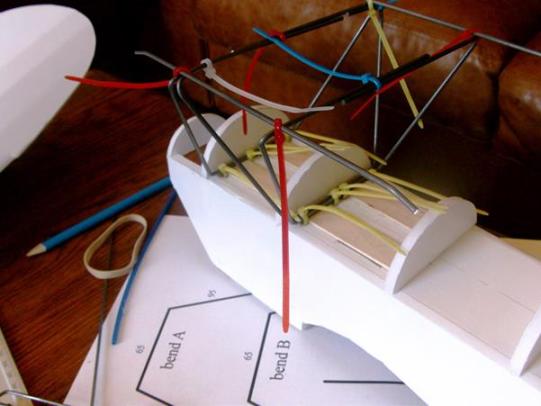
Start by bending–up your 4 cabane components. The two thicker frames shown above…
…and the two thinner cross–braces. Though I suggest you delay putting the top bends on these thinner cross braces until they are fitted and firmly held down on the deck. This will allow for any build variations and allow you a little 'wiggle room' to adjust the angle of incidence of the top wing.
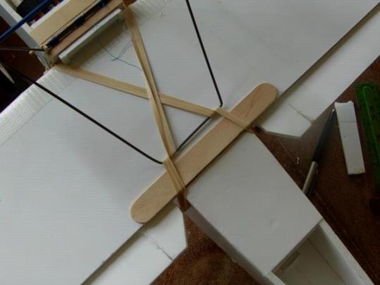
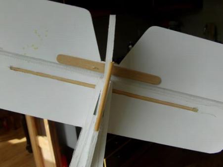
Apologies, I missed a picture of this part of the build but here's a very similar assembly from the Polikarpov Po–2, though the backward leaning cross–brace is missing!
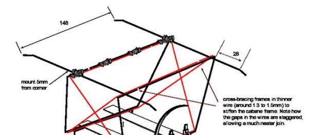
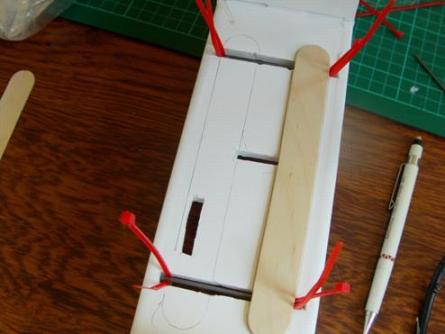
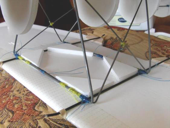
Trap the bottom of the wires with the zip ties, arranging them so that when the cross braces are in their final position, the joins will have staggered overlaps as shown. (The view in the plan is clearer.)
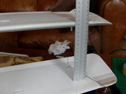
The next thing to do is to get the front cabane frame sitting vertical when connected to the forward leaning cross–brace. When you're happy, zip–tie the wires at the centre of the span to hold them steady and then thread and CA them together. After that you can place the top rails on the frame using zip ties as shown in the earlier photograph and then adjust the position of the back frame to get the rails sitting at the correct angle of incidence.
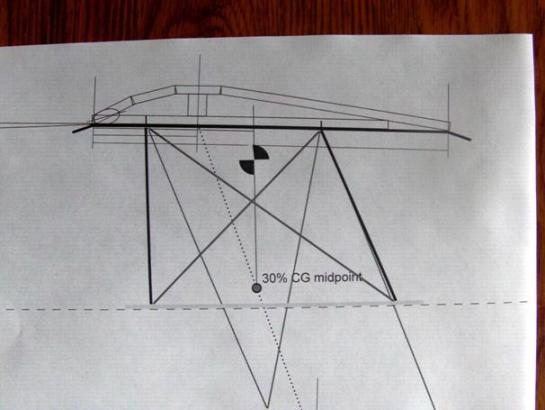
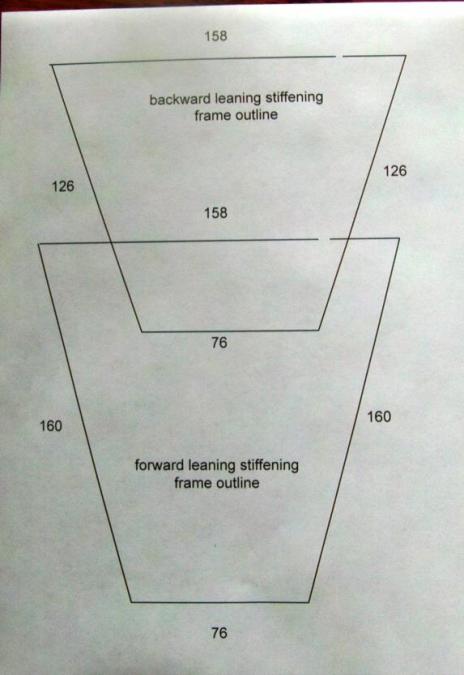
You can use the geometry drawing from the plans as a guide to setting it all up – the dotted line is the top of the fuselage deck. Fit the backward leaning cross–brace, making the bends to achieve this set–up. This is not precision engineering. If the incidence angle is out by a half degree or so, it won't make that much difference. If you need to start again, and need to adjust the bends on the backward leaning cross–brace, you can slide a sharp blade along the wire and through the threaded join, pick it off and start again. The thread needs to be tight, but not super–tight. The joint strength comes from the multiple turns and the CA filling all the gaps and binding the threads to each other. *(Plus see my note at the end of this section.)
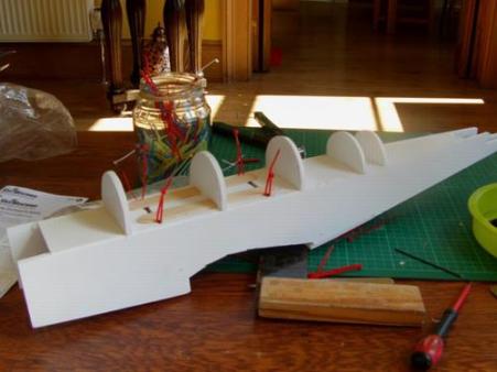
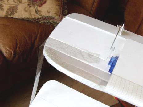
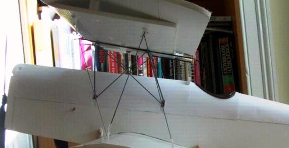
Here's the SE5 again – bottom zip ties have been tightened and snipped, and the wire to wire joins made up using wound thread and CA. I joined the cross braces with thread and CA as well, as that helped to stiffen the frame a lot.
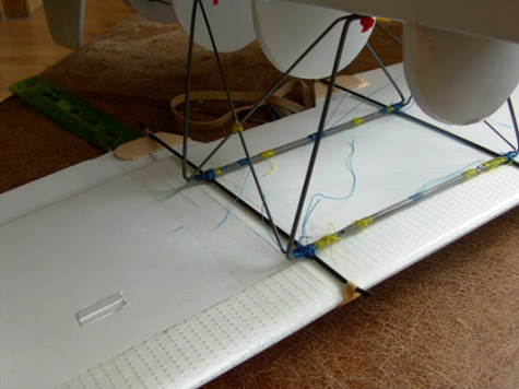
Here's another picture of the threaded joins. I've still to trim the loose ends.
With both wings 'elastic–d' in place you can fiddle about with the top wing, making sure it is centred, square to the fuselage and lined–up with the lower wing. This 'should' sit the top wing centrally on the cabane frame, but if you're frame is a little 'out' don't worry. The important thing is to get the wing in the right place – once it's flying nobody will notice a slight misalignment of the frame, but they will notice if the wings are askew. Once your wing is looking good and well aligned, carefully fit the wing centring pieces inside the rectangle made by the wires. If you look carefully you'll see I trimmed a tiny bit from the outer corners of each triangle to ensure good contact with the sides. Once the pieces have set, it'll be easy to remove and replace the top wing and get it realigned. These little triangles will wear over time and they can be damaged during a crash, but they are easily replaced.
*Geometry NOTE – In my assembly the front cabane element is tilted slightly forward. This was correct for my source drawing, but I have since seen a lot drawings and photographs that show these struts as vertical. Going with the majority, I've altered the final drawings and adjusted the component sizes to produce a closer–to–vertical front cabane. The actual position of the top wing remains unchanged, so the suggested CG will be correct.
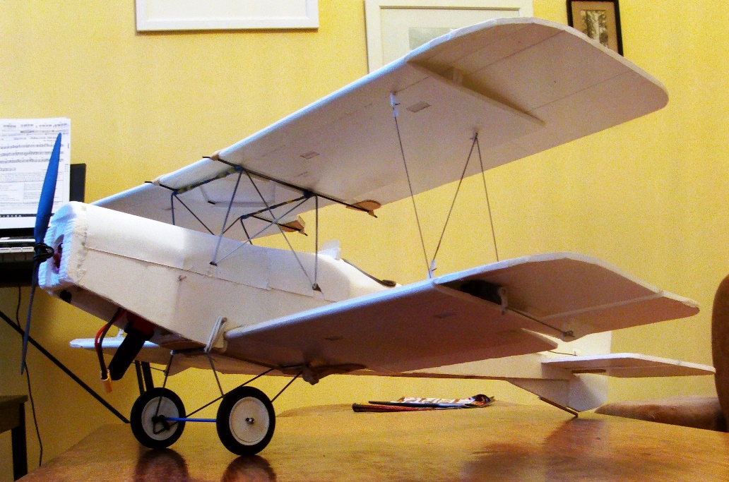
Interplane struts.
There's a good sequence to installing the interplane struts. First look at the top wing, back mount. This mount holds two 'struts' with modified Z–bend ends – one strut goes to the rear mount on the bottom wing and locates with a swing–in keeper. The other goes to the front mount and again locates with a swing–in keeper. This lower front mount also holds a strut with a modified Z–bend end. Note that the modified Z–bend is fitted as low as possible and the swing–in keeper is in the top hole. This keeps the wires from snagging each other. The last connection at the top front is a swing–in keeper. This sequence means there's never two swing–in keepers sharing the same mount.
I started making–up my struts; fitting the modified Z–bends at one end and leaving the other end 'long–enough' to work with and trim to size.
Top wing back mount gets two struts with modified Z–bend ends. Bottom wing front gets a single strut with a modified Z–bend end. 3 each side, six in total.
Once I was ready I made sure the wings were equally spaced…
…taping each end of the wing to keep the geometry steady. First I weakened the tape's grip/tack by pressing it to my jumper a few times. This makes sure the tape doesn't lift the paper from the wing when you remove it. Don't pull the tape tight, as this will flatten the top dihedral and increase the bottom dihedral. It doesn't need any real tension.
Here's the tape at the other end.
Now I can start fitting the swing–in keepers. I'm aiming to turn the wire through the top hole. You're after a loose fit – neither pulling nor pushing.
I found it easier to fit the swing–in keepers if the wire slants across the top of the servo arm. To make this happen; at the top mount the wire passes through from left to right, and at the bottom here the wire passes through from right to left. In effect the wire zigzags its way through the mounts.
Next I went to the other side of the plane and fitted the 'same' component. Continue in pairs until they are all done. Then remove the tape carefully!
You'll be surprised how steady it becomes once all the struts are in place. In flight any small deflection and bending of the wings will happen together, so there are no massive forces for the struts to cope with.
Details, details.
I put my servos in the cockpit area, though if you use a 'short' power pod there's plenty of room inside the fuselage to mount them upside–down on a little tray above the wing. Then the control rods can be run beneath the back deck to emerge through the sides of the fuselage underneath the HS. The only downside with this is you need to remove the wing to make any mechanical adjustments – but that's typical of many commercial models. Working in lighter foam board it may be possible to mount the servos further back.
Here's the control rod snakes inside the turtle deck. This is a fully enclosed compartment so these are needed. With stiff–enough wire you could just use four cotton–bud sticks as snakes; two at the front, and two at the rear. If you do go for a split system I suggest you cut a little access window just behind the second–from–left turtle deck former to help you thread the wire forward into the cockpit. At the back I notched the ends of the snakes into the side of the last little turtle deck formers and when I glued them in place I shaped the surface of the hot glue with a wet finger to replicate the former's original profile.
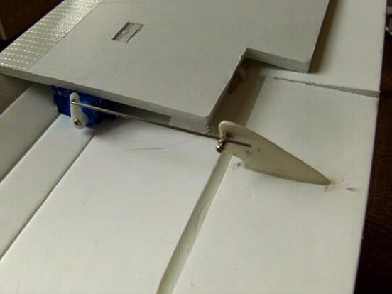
Aileron control rods and horns installed, and I finally remembered to cut my bevel in the wing instead of the control surface, leaving more material on the control surface for fitting control horns etc. These control horns are cut from old props.
The elevator linkage has a small meander in the wire to bring it away from the centreline. A modified Z–bend was easy to fit on this side. The screws go through into…
The lollipop stick glued underneath that joins the sides of the elevator – and again I remembered to cut my hinge bevels on the 'plane' side.
The rudder connects using a swing–in keeper, which proved much simpler to fit than trying to get a Z–bend through the hole. Again there's a little meander in the wire to bring it away from the centreline.
Turtle decks.
The turtle deck templates are included in the small component set.
The turtle deck is made from four sections. Before starting to glue, I did a bit of shaping to get a curve on the paper, then I went with Josh's most recent system of tacking the highest points along the centreline (just in front of the tail and the tops of the two formers behind the cockpit). Once the glue set, it was reasonably easy to glue down the curves, one side at a time, which just left a long straight glue bead on either side of the fuselage. Trim any projecting paper flush at the back of the cockpit. I later had an interesting thought about this section – if the paper had a series of gentle radiating folds bent into it, rather than a continuous curve, some of that detail would remain when the paper was glued, creating the impression of ribs?
Fit the cockpit turtle deck using the same system; tack the paper dead centre at the top of the curve, and then work down either side. This photo shows me halfway through trimming the paper flush with the next–along former.
Nose section is now in two sections. a short 'downward sloping' element in front of the cockpit, and then a straight element running forward to the nose. Cut the little slots around the cabane wires and prepare the sections with a bit of pre–shaping. The wires do get in the way, and this time it's easier to revert to the 'original' Flite Test system; first gluing or taping one side before applying glue to the curves and pulling the paper over the full curve. It's much easier if you remove the wings!
Radiator detail.
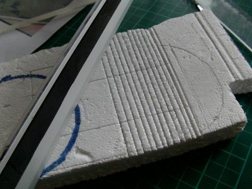
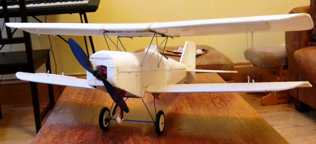
I fitted a polystyrene foam panel to the front. The distinctive radiator detail was pressed into the foam using the edge of a rule.
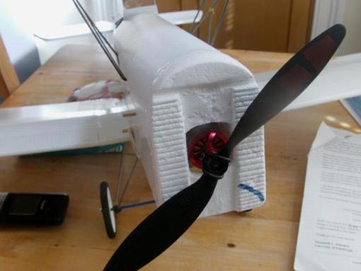
After carving out the depressions it looks a little better. The new nose profile is not as deep, but you'll have a foam board backing element from the plans to help you get the size right if you want to add this detail. The foam is finished with a couple of layers of dilute PVA to strengthen it and allow it to be painted. If you don't fancy carving polystyrene, just use the simple blank nose panel in the plans. you could glue shaped elements onto it and a little sanding along the top to round the radiator would work wonders. Some of the SE5's had very rounded noses, and you could just laminate two full layers of foam board and then sand them into a more bulbous form – curving–in at the sides and the top. Have a look on the internet for ideas.
Power pod.
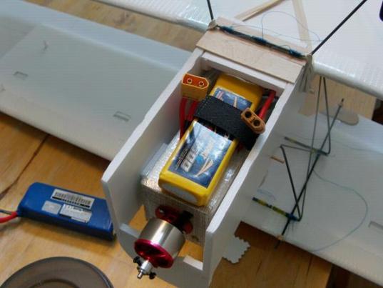
If you stick with the cockpit mounted tail servos, the plane will take the standard Flite Test power pod. The pod shown is actually half the length of a 'normal' one. I've shown a 1500mah LiPo in place, but there's plenty of room for the 2200mah one sitting on the table. Because the power pod is so short, I added a couple of 'cheeks' either side of it to help keep it centred. With the new tapered nose, the batteries are not as well hidden as in this photograph, and you might consider reducing the depth of the power pod to keep them a little higher.
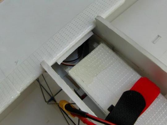
Here's the undercarriage mount removed, and you can see how short the power pod is. I've been shortening all my pods in an effort to reduce any tail moment they might create. Getting these heavier foam board planes balanced can often involve adding even more weight, so every little helps. I later added cheeks either side of pod here as well.
Extras!
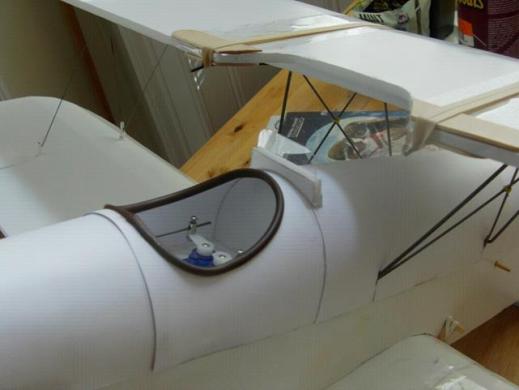
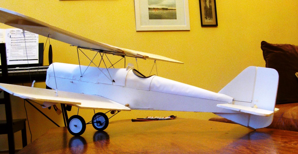
This picture shows the cockpit edge, which is made from hollow electrical insulation sleeving that has been slit along its length. This coloured tubing is placed on the ends of mains wiring to notify the 'change' to the wire's designation/function – a wire with this brown sleeve would be 'live' in the UK. Mostly people see this sleeve in yellow and green for terminating the exposed earth wire in mains cable, but it does come in a number of other colours.
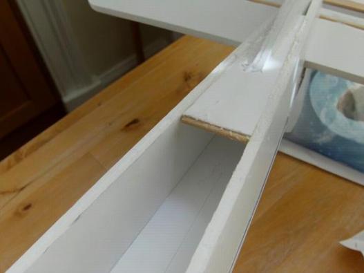
In this picture you can also see the simple windscreen, and above it the extra reinforcement I added to the trailing edge of the top wing. I felt the single layer of foam was vulnerable to pressure from the elastics and the mounting rail, so I added little bits of tongue depressor above and below.
I didn't bother with a head rest – you can fit one, but SE5's were also flown without them for better visibility.
And finally…
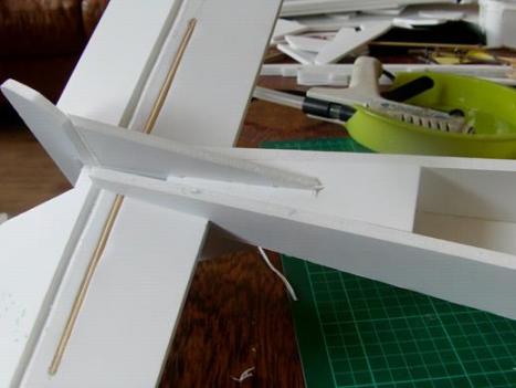
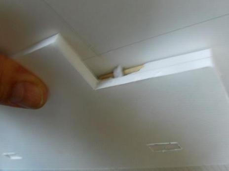
One last little mod – a skewer cross–bar on the tail stiffener.
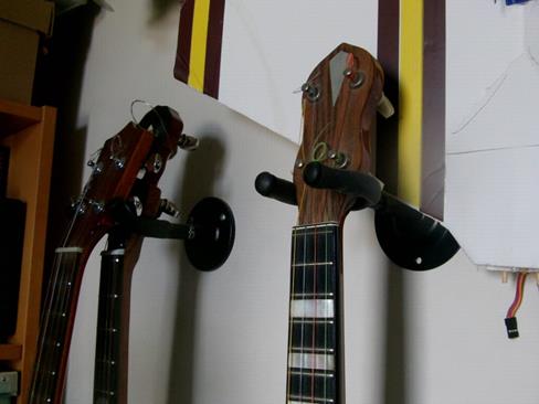
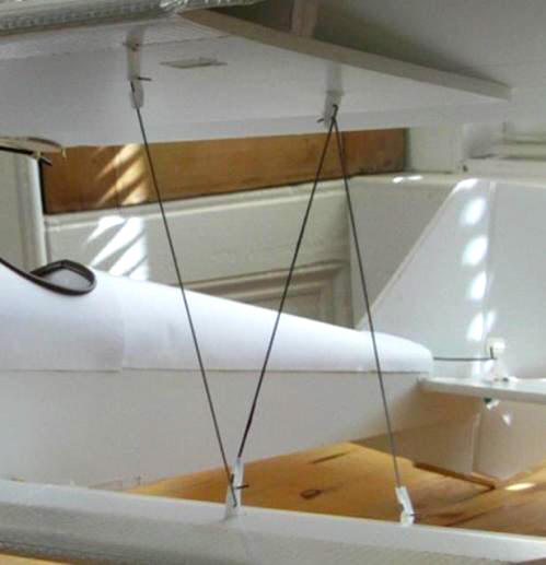
I double–up my Uke and banjo hangers as plane hangers!
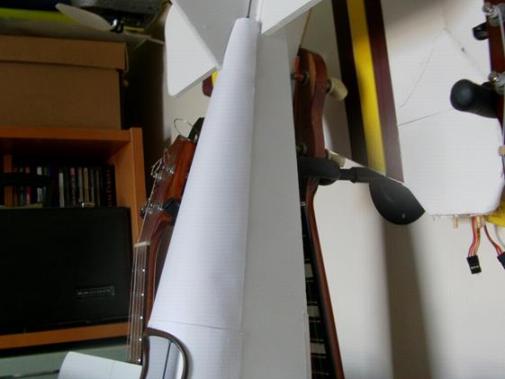
…and when I hang up my planes the little bit of skewer stops the foam getting dented.