Wingspan - 840mm 33.1 inches
Length - 600mm 23.5 inches
AUW - 1050 grams 37 ozs with a 1500mah LiPo
Drive - EMAX GF2215/20 1200KV motor with a 9 x 4.7 SF prop.
Plans - PDF file. (Can be printed on A1 foam board.) AVRO 539b.
(Build instructions in Tribewt2 article.)
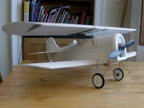
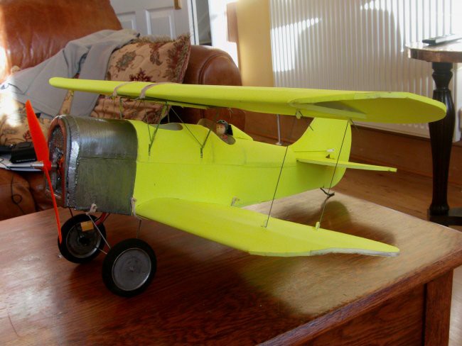
In this photograph the plane appears here as a tail dragger, but as you can see below it was originally designed and built as a seaplane to compete in the 1919 Schneider Trophy event held in the UK at Bournemouth. I don't fly off water, so the obvious choice was to build as a tail dragger.
To whet your appetite, have a look at these videos of the plane in flight;
And a little more fun in the air;
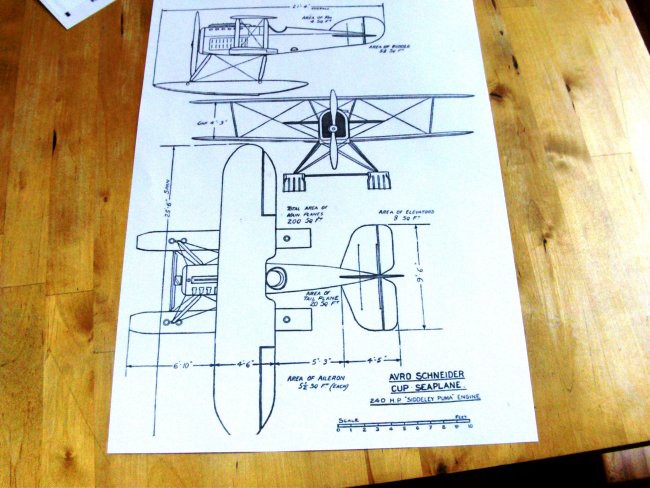
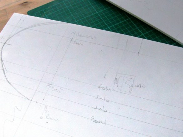
It all started with a plan… courtesy of the interweb.
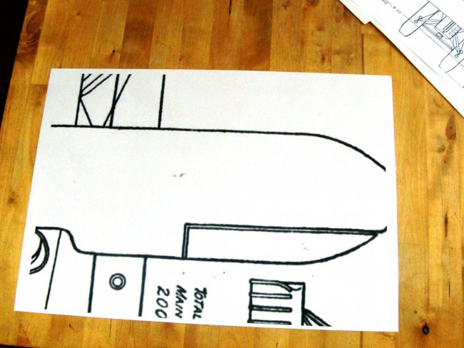
Next, how big to build it? So that I could make the wings in a single piece I re-scaled and printed the drawing to make use of the longest edge of my A1 foam board sheet (841mm). Using the Baby Blender for comparison - the wing chord of the AVRO 539 is less, but the wing span is greater. Doing the sums it turns out the wing area is almost identical - so the wing load will be very similar to the Baby Blender.
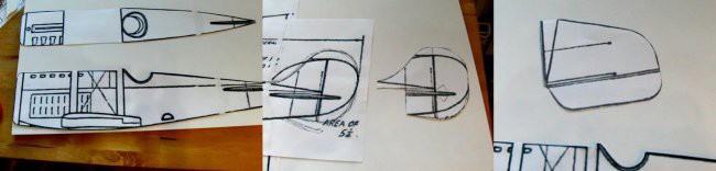
This wingspan decision dictated all the other sizes. I cut out the pieces from the scaled print-outs and transferred the outlines and hinge detail etc. to the foam board.
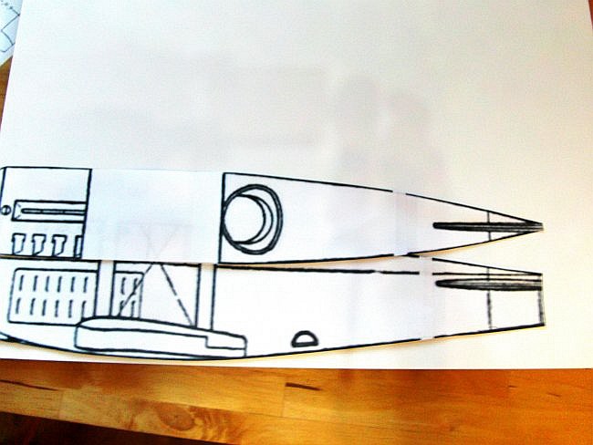
I used the plan and elevation to help lay out a typical FT style fuselage – top and two sides. To create the gradual curve on the rear of the fuselage I took the top panel all the way to the tail, which meant using a 'B' type fold.
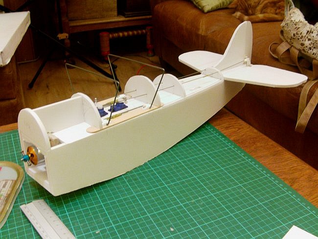
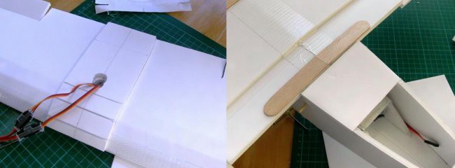
Here's the fuselage with all the basic components added; tail, servos, power pod, turtle deck formers and top wing support. I added a double-layer cross piece at the front to rest the undercarriage against. Note – the servos are mounted well forward to help with balance.
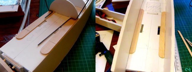
The top wing support is screwed into 4 tongue depressors – 2 glued on the top and 2 trimmed ones on the inside.
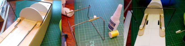
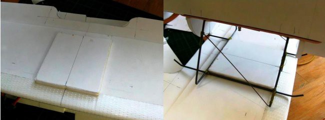
The wing support frame is made-up of two identical pieces of bent wire that are bound together with thread and CA glue.
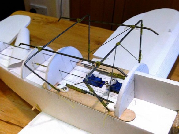
I hoped the frame would be stable enough to support the wing but it was a bit too springy, so I added thin bracing wires to create stiff triangles. The top ‘skid shaped’ wires are for attaching the wing elastics. The plans use a slightly different system, which evolved from this design. You can see the assembly detail in the build sequence for my Polikarpov Po-2. The end result is the same, a stable wire platform to rest the top wing on.
Knowing the chord and wingspan, I was able to lay out a typical Armin/FT Cruiser type wing. The only addition to the basic design are anchor points for the struts. I described them as ‘brace’ points in this drawing. This is the bottom wing, which isn’t as wide as the top wing.
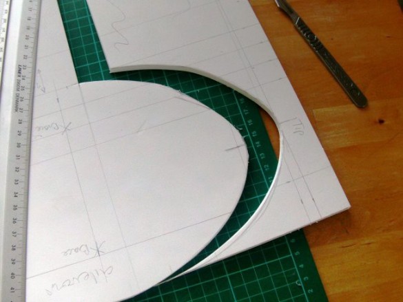
After I cut this first wingtip, I used the off-cut as a template to draw the other three.
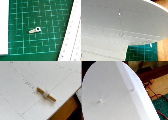
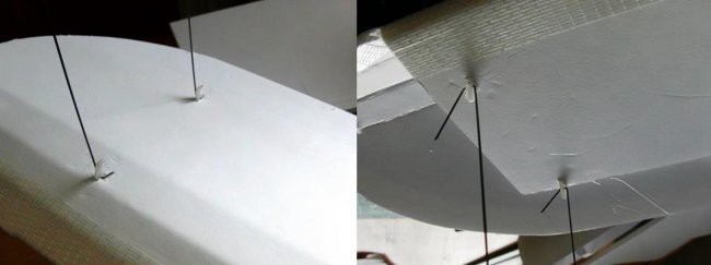
I use spare servo arms as the attachment points for the struts. These poke through holes I cut in the foam, and are glued on the inside of the wing with a short length of skewer through the end to spread the load. The bit that sticks out has useful holes for fitting wire to. I didn’t intend these to be too structural, just help maintain the spacing between the wings - and they definitely add character.
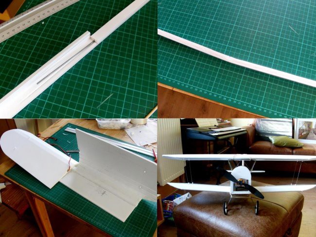
The upper wing is flat and the lower wing has dihedral. To make-up the lower wing I bent a piece of 2mm wire to the correct dihedral angle and embedded this in my wing spar. This made assembly much simpler as the spar helped to produce the correct dihedral as the wing was assembled. The wire adds some strength, but was mostly just an aid to assembly. Again, the plan detail is slightly different, using an on-edge spar with locating tabs that fit in slots in the underside of the wing. Fitting wire reinforcing in this later spar is actually simpler.
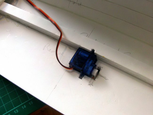
The aileron servos were sunk into the wing during assembly.
The bottom wing centres using a pad glued to the top of the wing, which fits between the fuselage sides. The back rests up against a stiffener running across the fuselage.
The top wing centres using this rectangular pad, which fits inside the wire frame.
I used thin wire to make-up the struts that space the wings with a modified Z-bend at one end. In this model I left the ends at the top a bit longer to make it easier to get them in and out using a kind of 'spring fit'. In later models I refined this to use the more familiar right angle bend with a small swing-in keeper to hold the wire in place.

Here’s the tail detail. I added a strengthener inside the fuselage, and included a little cut-out to help stiffen the rudder keel. I also added a steering tail skid using my simple tail steering method.
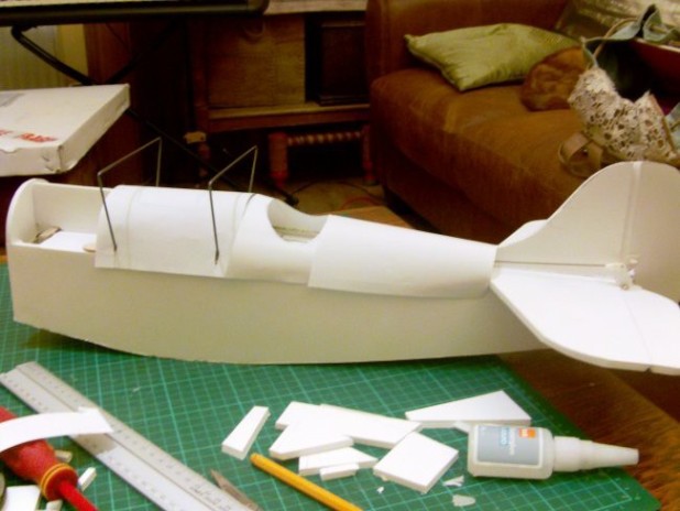
Here’s a test fit of the paper templates for the turtle deck. I later included a hole above the servos to avoid the need for a removable section. The plans place the servos in the cockpit area, which makes things a bit neater.
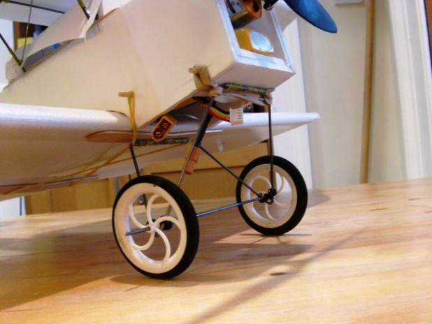
The undercarriage is held on by elastics. At the back I use an extra loop in the wing elastics and at the front a dedicated elastic/skewer. The wheel axle is sprung by passing it through two twisted prop saver rings. The landing gear frame is made-up from two mirror-image parts bound together using thread and CA.
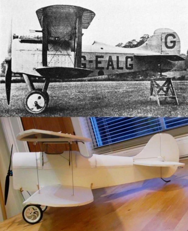
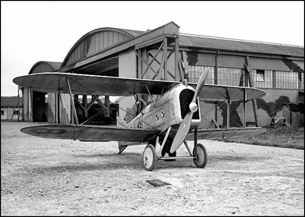
I like the overall look of the plane - here it is in comparison to the original.
Almost there - the whole plane was sprayed with clear matt varnish before the maiden. In this picture you can see the servo access opening hidden under the top wing. I blanked out the wheel spokes with foam board and card for a better look using my old-style wheels method.
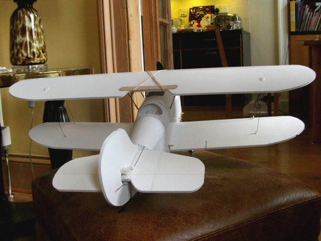
Foam radiator and headrest fitted - just the windscreen to add to the cockpit, and a final paint job.
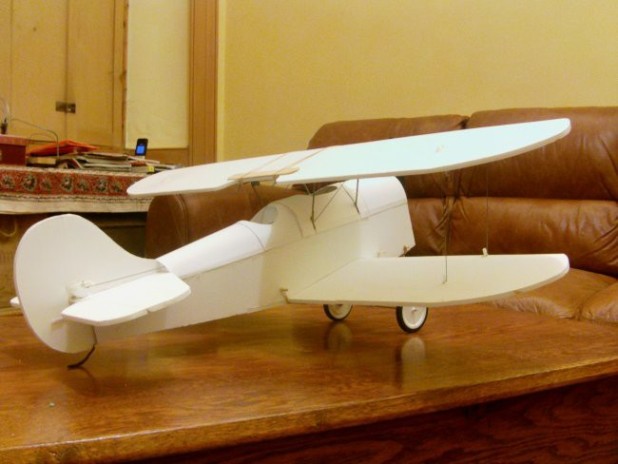
I'm very pleased with how this plane has turned out; compact, classy and stylish.
Here she is with a headrest, windshield, paintjob and a pilot. Those are bigger wheels on the front, which have mostly allowed 'proper' landings. Have a look - 1:40 in the first video - and you'll see how well it can land given ideal conditions. You might notice the nose is slightly remodelled. I had a prop-saver fitted, and the prop got knocked off-centre without me noticing - next time I powered-up I 'shaved' the front end down. A little outline plate cut from pizza base foam has neatened it up a bit.