Wingspan – 1034mm 41 inches.
Length – 700mm 27.6 inches.
AUW with 1500mah LiPo – 1046 grams 37 ozs.
Drive – 1270Kv 200W outrunner with 9 x 3.8 SF prop.
Plans – PDF file. (Can be printed on A1 foam board.) Polikarpov Po–2.
Before reading–on, have a look at this later video showing how well the plane flies once it is properly trimmed-out and balanced:
Now here's two earlier videos. The first part of the maiden shows a range of problems which are then fixed on the field (1.18) to produce a very smooth flight experience & the second video from a later day out includes adjustments to motor down thrust and balance which produce great results. This plane is now a real pleasure to fly.
Maiden:
Flight testing:
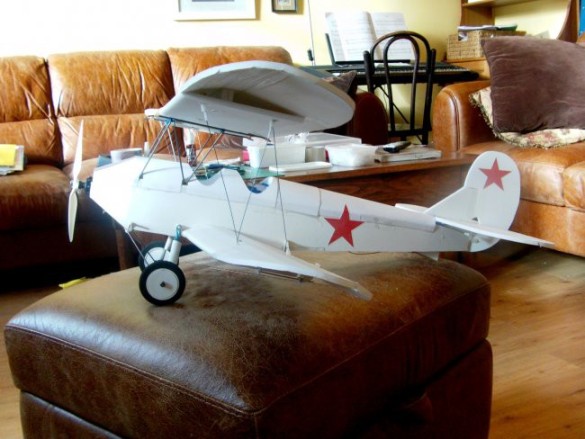
I decided to build this biplane because of its distinctive design and rich history. The aircraft was designed by Nikolai Polikarpov and the prototype first flew in January of 1928. Serial production in the Soviet Union started in 1929 and ended in 1953. The original U–2 classification was later altered to Po–2 to acknowledge the designer.
License–built versions, CSS–13's, were still produced in Poland until 1959. The upper estimate for build numbers is around 40,000, which apparently places it at the top of, or very close to, the all–time record holder for production figures of a single design. Pre–WW2 it was used as a trainer, a crop–duster, and many other civilian and military uses before serving right through WW2 as an air ambulance, an aerial reconnaissance platform, an artillery spotter, a target tow and a light bomber, to name of few of its roles. Due to its STOL capabilities it was used for supplying Soviet partisans behind the front line and, famously, it was used as a night bomber flown by female crews, cutting their engines to glide near–silently over their targets to harass German positions. Though vulnerable to more modern fighters the Po–2 was highly manoeuvrable and flew at speeds slower than the stall speeds of the opposing fighters, making it a difficult target. Having said that, its slow–flying made it very vulnerable to ground fire. A single bullet in the right place was enough to down the plane, but equally it could be riddled with bullets and still keep flying.
As late as the Korean War Po–2s were flown in combat by the Korean People's Air Force. UN forces called the Po–2's night attacks 'Bedcheck Charlie'. There were some notoriously successful bombing raids where UN planes were destroyed on the ground by Po–2 attacks. The wood–and–fabric–construction of the Po–2 gave only a minimal radar echo, making it hard for opposing night–fighter pilots to find. The Albanian Air Force operated Po–2's until 1985. This little potted history is just a glimpse of the longevity, reliability and functionality of this very successful aircraft. From the modelling perspective there are practical reasons for choosing this aircraft. The fuselage is square–sided, making it easy to copy in foam board using the familiar box fuselage and turtle–deck formers with paper skin. The cabane system I first used on my AVRO 539B has been refined in this build and can easily be transferred to different biplane designs. Regarding detail, the only significant drawback is the exposed radial engine on the front, but that was reasonably easy to fake–up using black nylon washers on wooden spines.
In terms of flight characteristics, the plane is very stable; the staggered wings give a very large effective chord, it also has dihedral on both wings and a long fuselage, which all help with stability.
So, where did I start;
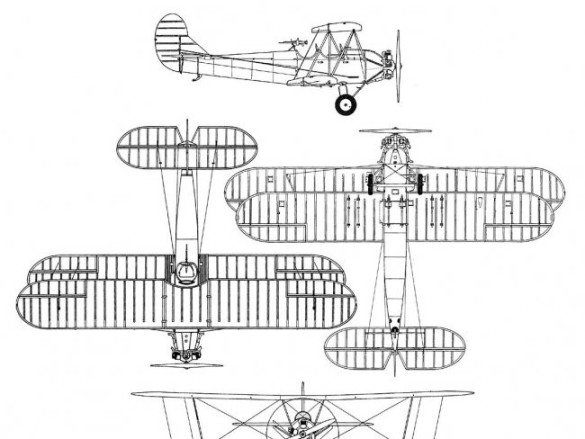
First I found a good 3–view on the internet…
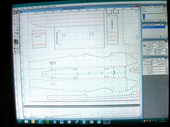
…which I imported into Adobe InDesign, a Desktop Publishing package. This software uses the same basic drawing interface as Photoshop, which allows layering of the drawings as they are created.
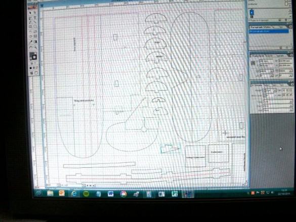
I made my 'workspace' the same dimensions as my A1 foam board (594mm x 841mm) and scaled the 3–view up and down to see how the larger components would fit on the foam board. I hoped the plane could be made from two sheets of A1 foam board and after trying a few wing sizes in the available space I came up with a 1034mm wingspan version (just under 41 inches). For comparison my AVRO 539B has a wingspan of 840mm (the long edge of the A1 sheet), and my Velie Monocoupe/Morphocoupe a wingspan of a metre (two half wings from the shorter edge of the A1 sheet).
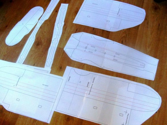
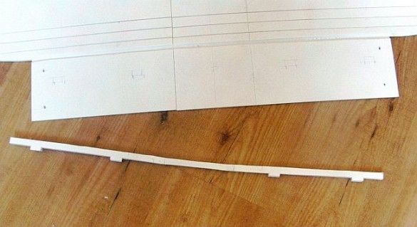
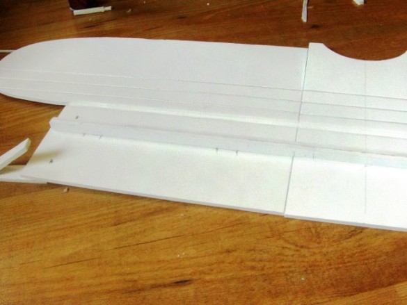
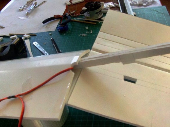
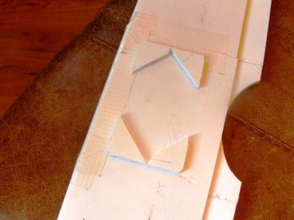
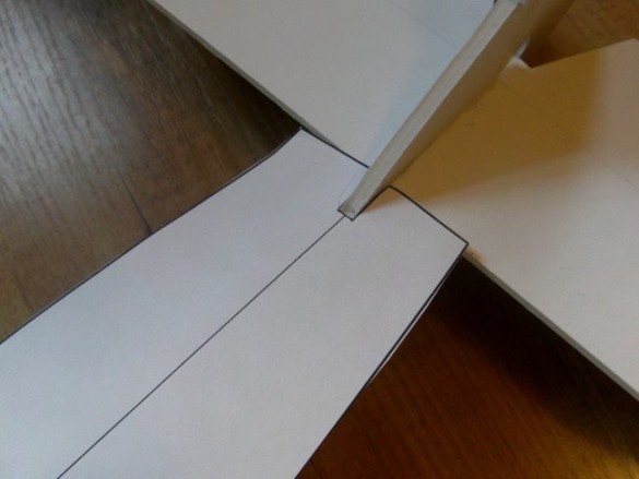
After copying the profiles and sorting all the assembly details and geometry; fuselage, wings, cabane frame, interplane struts and undercarriage, I printed up my components on A3 paper and stitched them all together with clear tape. Note the top wing, shown in the foreground here, is made from asymmetric parts; one side includes the centre flat that will sit on the cabane platform, the other side is just the outer wing.
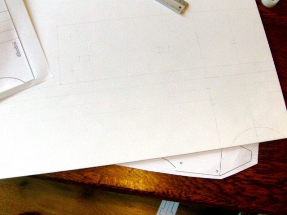
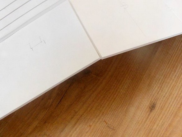
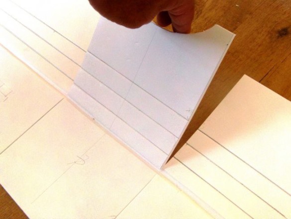
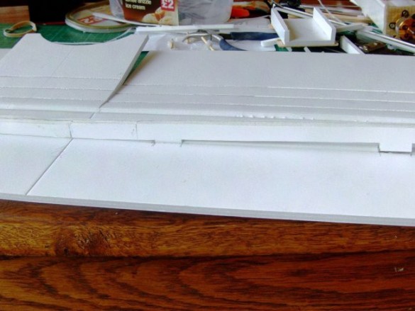
I transferred the paper detail onto the foam board…
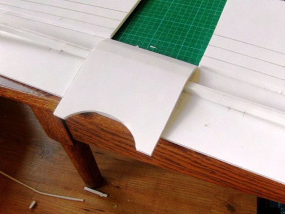
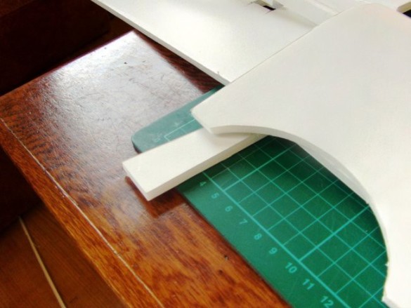
…and then began to cut out all the components. This should be familiar to anyone who has built the core Flite Test models. At this stage you might choose to remove the curve from the rear fuselage sides – I've left an optional line on the drawing. Removing the curve makes fitting the rear section of turtle deck a lot simpler, but does narrow the tail making it slightly weaker.
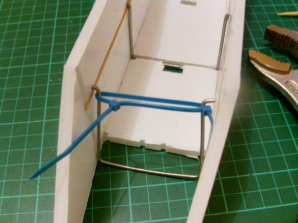
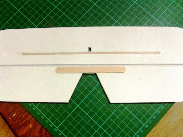
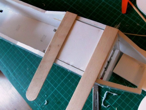
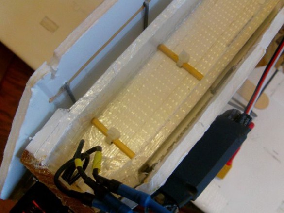
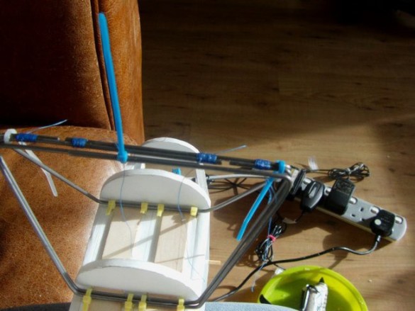
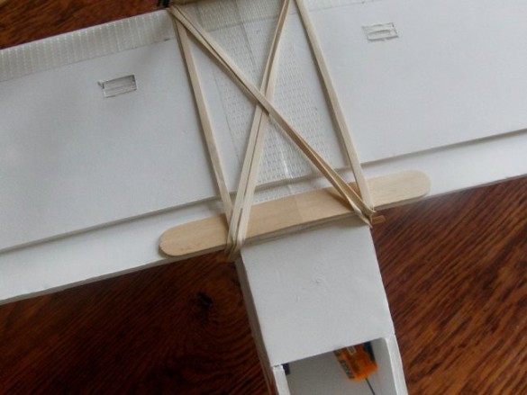
This is the method I designed to integrate the cabanes into the foam board fuselage. It uses two transverse 'rail' mounts which are hooked onto skewers embedded in the fuselage sides. This works a bit like a car roof–rack, and the cabanes are 'tied–down' onto the rail mounts using zip–ties. The cabane assembly also sits on top of a platform made from tongue depressors, which spreads the loads and prevents damage and wear to the top of the box fuselage. Though a simpler connection by gluing the cabanes directly into the top of the fuselage would also work, it would have little resilience to shock and flight stresses. Any shock loading will concentrate at the glue connections (instead of spreading into the bulk of the fuselage) and the model is likely to have a much reduced lifespan.
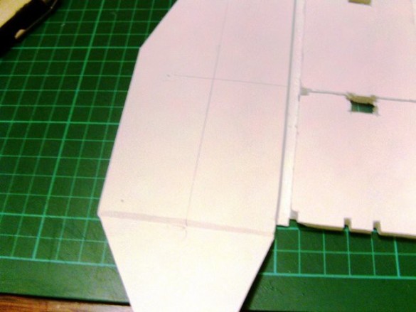
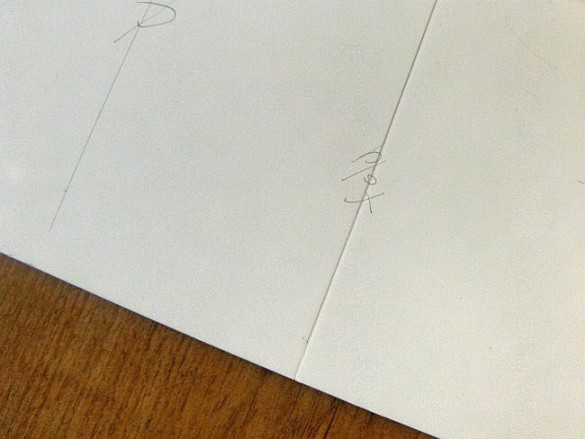
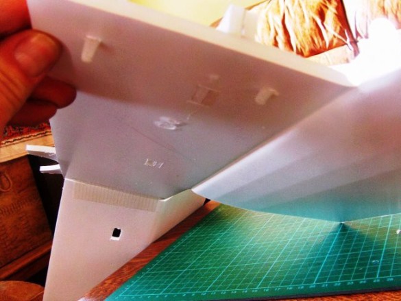
I marked an initial position for the skewer on the insides of the fuselage. In this first position I quickly realised the skewer wasn't far enough down the fuselage side, for reasons I'll demonstrate shortly.
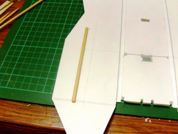
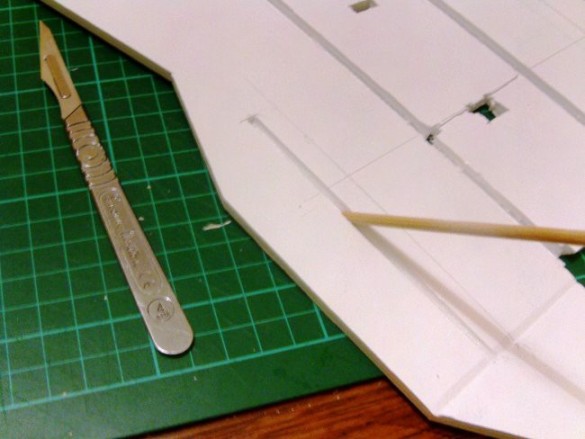
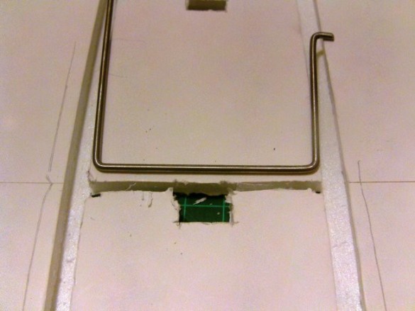
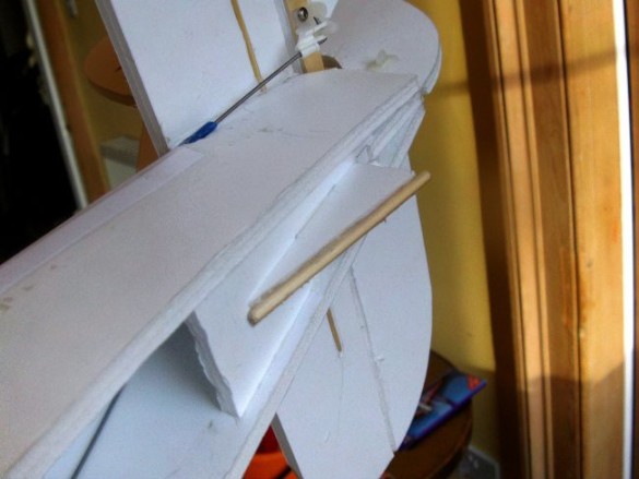
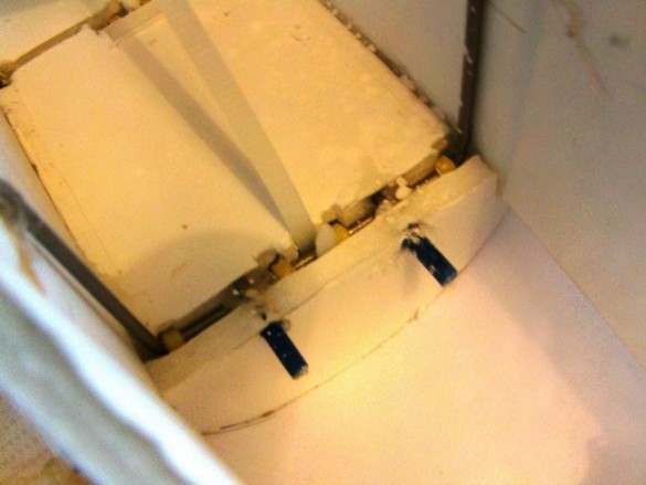
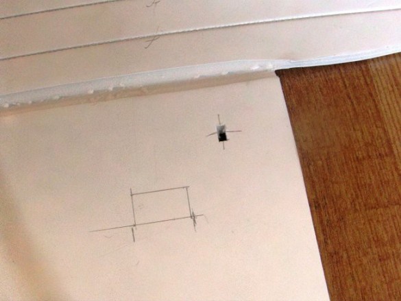
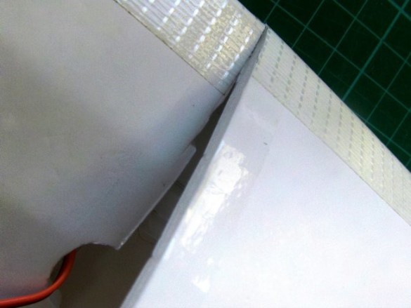
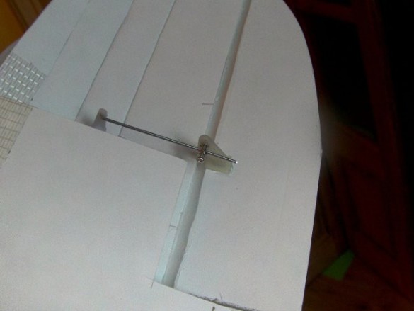
This was the final position I chose – the dimensions will be correct in the plans, but as this is the test build there's always changes happen as the build progresses. I cut a length of skewer, with a reasonable overhang at the back and a little projection at the front to allow it to 'catch' on the corner fold where the nose starts to taper. This 'length' helps to spread the forces coming from the wing, through the cabane frame and into the fuselage. On the top deck you can see some distinct nicks in the foam at the front, intended to accommodate the zip–ties. These were just a 'fiddly' nuisance and this is now just a slot on the drawings.
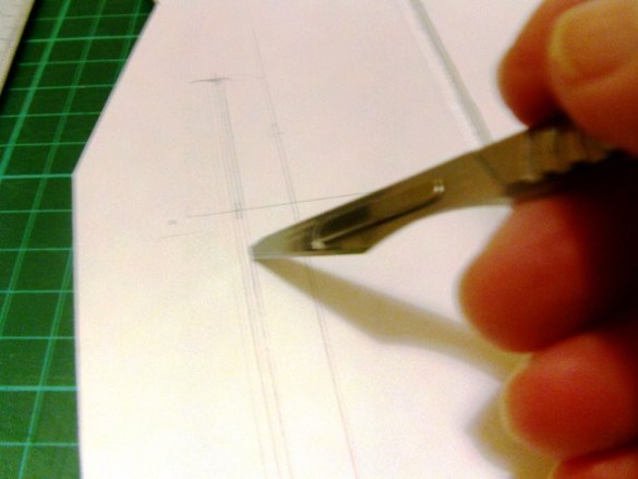
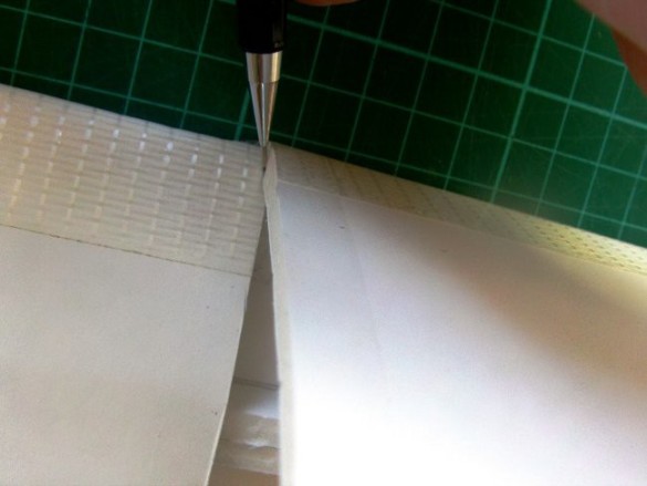
(Apologies for the fuzzy picture.) With the skewer in position, I drew along its sides and then made angled cuts following these outside lines. I can't give exact sizes, as all these skewers are slightly different.
This created the first 'v' shaped hollow…
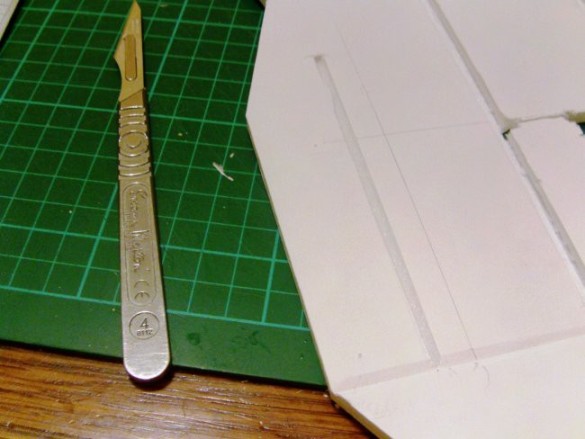
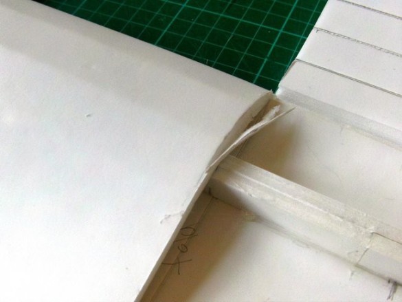
…which I then scored with the skewer until it fitted flush in the slot.
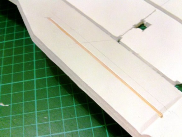
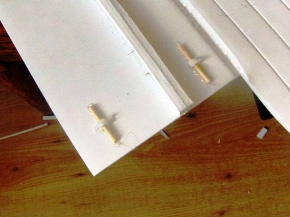
Skewer glued in place and ready for the next stage.
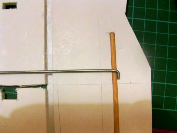
The cabane mount is going to catch on the skewer but I don't want it to stick out of the side of the fuselage, so the first right–angle bend is only about 4–5mm long. This 2.3mm wire produces a tremendously strong and almost rigid cabane frame. I think you could get away with lighter wire, 2mm, but the frame would have a little more 'spring' to it. Nothing you'd notice in flight, but the extra flex might cause the thread and CA joins to release over time. No problem if you go for a copper wire and solder join.
The next bend needs to place the wire flush with the top of the fuselage deck. This is a 'B' type fold, so I took the wire to the edge of the folding slot. I've given a size in the drawing, but you really need to check against your fuselage for a good fit.
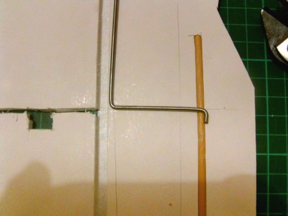
For the next bend the mount needs to span the inside of the deck. There's a little 'wiggle–room', but make it too wide and you'll need to dent the fuselage sides to get it to fit, or make it too loose and you leave less space for your power pod.
After the last bend (to match the first leg) it's time for a test fit. All looking good, though in this photo I see I need to bend the nearer leg in a little to make sure it's square. I wouldn't want it to spring open the sides of the fuselage.
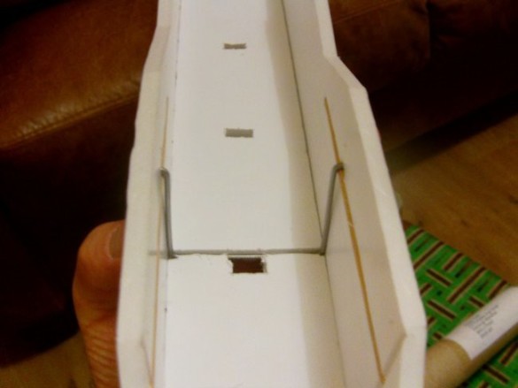
Here's the wire in place for a final test fit. I used a sharp skewer and a 'wiggle' to poke holes in the foam where the ends of the wire hook over the skewer. Take care not to go all the way through the fuselage. It'll be much neater if the ends of this wire remain hidden. After you've made–up a second 'identical' cabane mount, you can glue–up the box fuselage. You could glue it up with the mounts in place, but that would be very fiddly. Don't worry, there's a 'neat' way to do it after the fuselage is formed, so go ahead and glue it up without them.
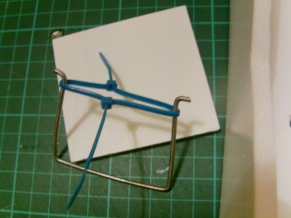
To get the wire in place you need to stop the ends sticking out and catching the fuselage sides. This is done by pulling the mount's legs together against the natural spring in the wire. I've used zip–ties for this. Now you can see why I moved the skewer further down the fuselage, it allows the legs to be longer. If these legs were too short it would be impossible to get them to bend and still spring back into shape.
Position the mount carefully and snip the zip–ties to allow the legs to spring into position.
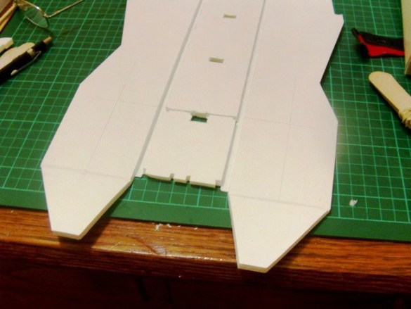
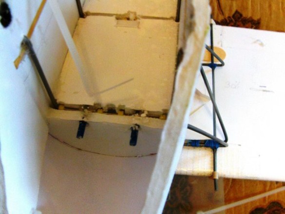
Mounts installed. As with all the builds using a removable power pod, now is a good time to fit your CUSTOM pod to get the exact position of the tabs and slots. I only later decided on a custom pod, so read ahead, see what this looks like and make it up now! The tabs should locate in the normal positions shown, but if your pod is slightly wider or narrower it's not so easy to squeeze it into place – better to make it fit now. This first turtle deck former closes the slot for the front cabane mount, so I installed it to keep the mount in place.
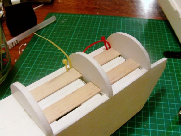
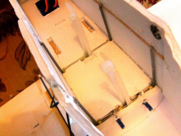
Then I installed the nearer of the turtle deck formers and cut lengths of tongue depressor to fit between the formers. Two popsicle sticks side–by–side would do the same jobs. Note the centre turtle deck former has cut–outs to fit over the tongue depressor – adjust these as necessary to fit your version. I've looped a couple of zip–ties around the cabane mounts to show how everything fits. You need enough space to get a zip–tie through and around the mount so don't put those wooden elements too close to the edge of the fuselage.
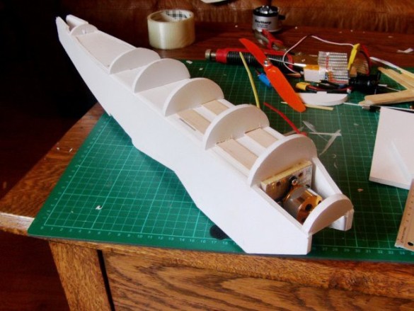
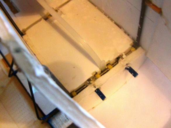
Moving–on, because the fuselage sides form a curve, I ran the curving inner deck all the way to the tail. As I mentioned earlier you can eliminate the curve and make the sides straight, with a single shallow fold just where that last big turtle deck former is, but I like the curve, and it does make the tail a little stronger. There are alternate tab and slot cut–outs in the drawing of the horizontal stabiliser. The solid ones are for the curving fuselage, so you need to choose the holes you need. And if you don't use those alignment holes (I didn't), you need to trim the tabs from the ends of the fuselage sides. At this point, don't glue that very last little turtle–deck former until you are ready to fit the tail. As this was a test build, I also left extra material around the lower wing cut–outs until I had an actual wing to test in the space. This is probably good practice as different people's wings do seem to turn out a little different. Here you can see I've fitted a 'classic' power pod in this photo, but as I mentioned earlier I decided to use a custom pod to help with a battery fitting problem I encountered.
Horizontal and Vertical stabilisers are quite simple, following familiar techniques for hinges and joining. Because the horizontal stabiliser is a big span, I added a skewer to reinforce it. I bedded this in just like the previous skewers in the fuselage sides. There's the familiar popsicle stick, spanning the two halves of the elevator. (I keep forgetting, but it's usually better to cut the hinge bevel on the 'plane' side, which gives more material on the elevator for fitting control horns etc.) I modified the component drawing to include a bigger locating slot for the tab on the vertical stabiliser, and added the option of slots for tabs on the curving fuselage sides.
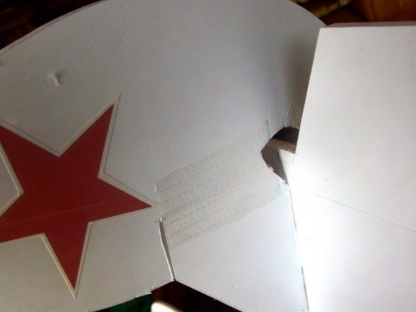
With such a large balanced rudder there's not much length of hinge, so I decided to reinforce it with strong packing tape.
All hinges cut and acting freely, so it's time for a test assembly of the tail. Looking good, even though this version doesn't have all those fancy alignment slots and tabs. The front of the Vertical stabiliser locates in the end of the fuselage deck, but it still took a bit of care to get the tail assembly centred when I glued it all up. Of course the first step is to join the vertical and horizontal stabilisers, making sure they are square.
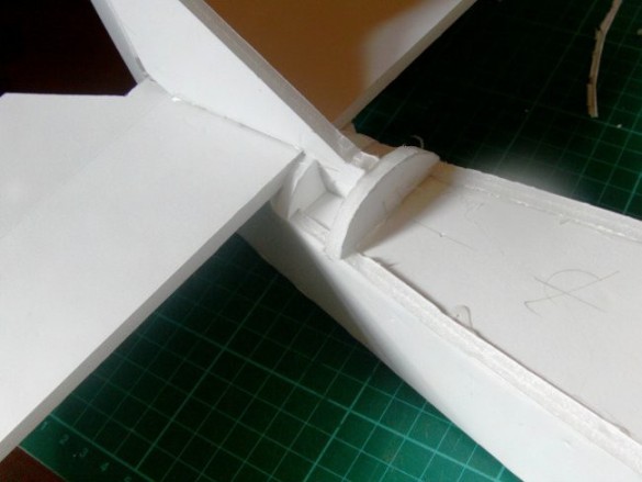
Tail assembly 'carefully' glued in place, and I added a couple of little deck formers right at the back.
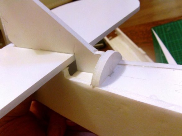
Actually a later picture, but now is a good time to add the tailskid mount stiffener panel into the tail, though I suggest you delay fitting the triangular skid component until later to make it easier to handle the fuselage.
The end of this little tailskid panel locates on and centres the lower 'keel' element of the rudder.
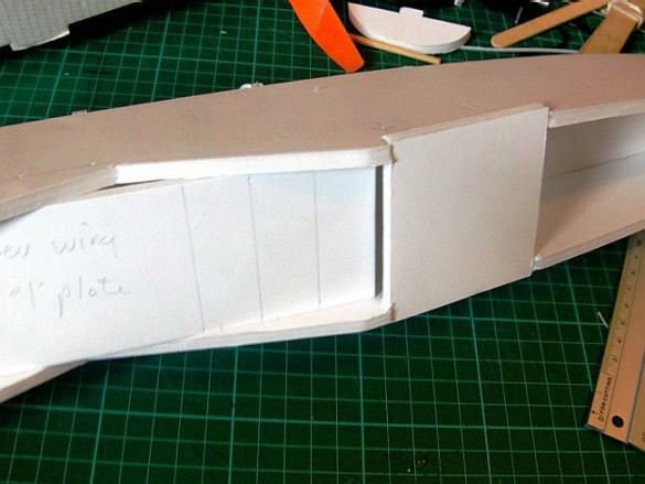
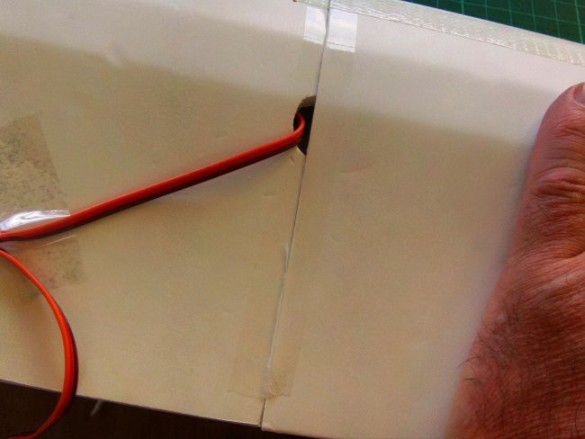
Using the 'lower wing top plate' to help establish and maintain my fuselage width, I added a cross member just behind the wing. Once it's set there's a second plate fits inside the fuselage, right on top of the first plate. The wing elastic skewer sits on top of this second plate making it extra strong.
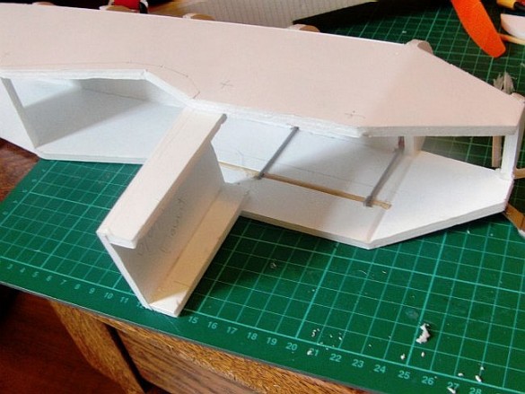
In front of the wing I'm adding a hatch–come–undercarriage mount. This is a little box folded up to fit between the fuselage sides.
I'm gluing tongue depressors across the base of the box for the wire undercarriage to rest against.
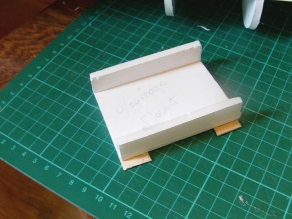
The tongue depressors are cut to length so that they project enough to sit on the fuselage sides.
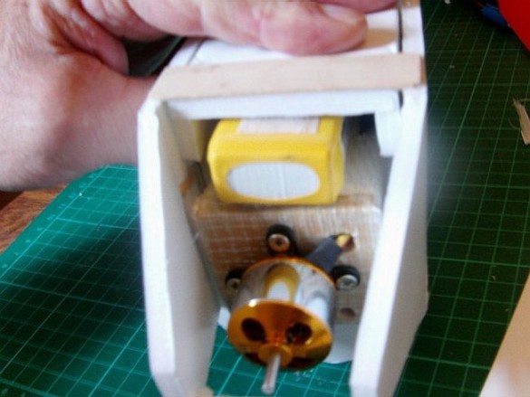
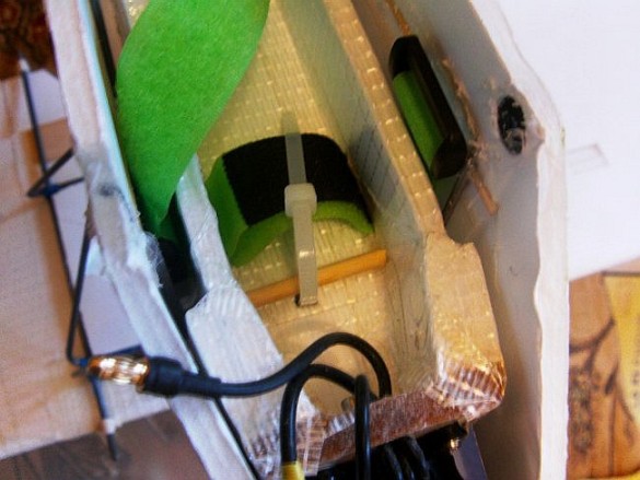
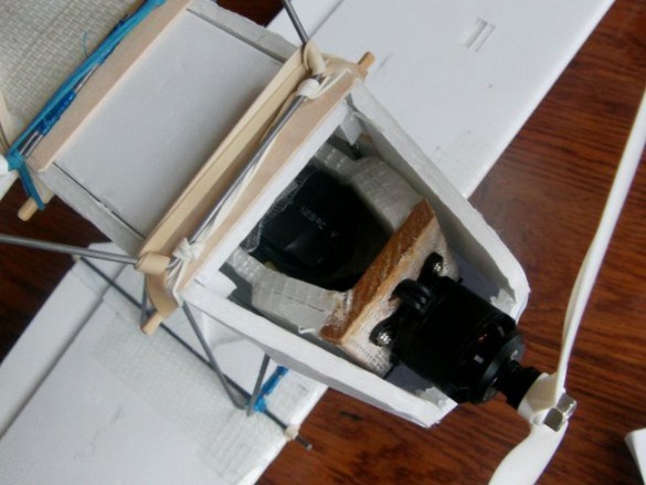
A test fit of my 1500mah batteries shows I have barely enough clearance, and these are unusually flat batteries. The only way to make more space for larger batteries was to modify the power pod.
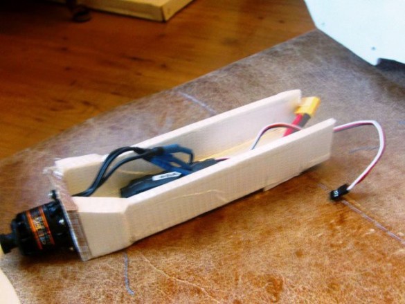
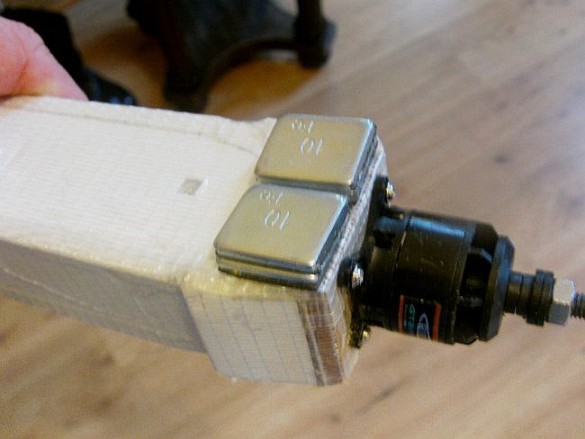
This is my solution. As well as being shallower, the hollow faces downward.
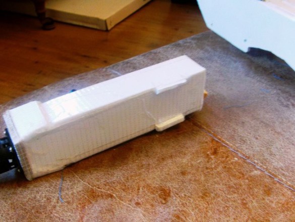
There are the locating tabs on the top, ready to fit in the slots in the box fuselage deck.
The pod is held–in by short lengths of skewer with zip–ties that wrap around the cabane wires. OK, it's not a quick release system, but it is replaceable as the ties can be snipped and re–fed.
Here's how. First bend back the narrow feed tail of the zip–tie…
…then push the folded end through, so that the tail snaps open against the turtle–deck former…
…and pull back until the tail re–appears on the other side of the wire. Grab the tail with long–nose pliers and pull it through. Easy! (OK, it's a bit fiddly, but it's do–able.)
Ready to re–fit the pod. You can also see the locating pins for an 'original' pod. These are not required now, but it would just make a mess pulling them out. You won't have these on your build.
Post–maiden service complete – battery strap fitted, and more down and side thrust added to the motor. I'm ready to tighten the zip–ties.
I also added a bit of weight to the nose to help get the CG right. I'm using one of the heavier foam boards and the downside is I often need even more weight to counteract the tail moment. A build in Dollar Tree or similar foam board will be a lot lighter than my plane, and may not need this extra weight. Were I building this again, I'd hold off fitting the nose and cockpit turtle decks until the plane was fully fitted out and almost ready to fly. Then I could fit any balance weights without removing the pod. Back to the actual airplane build… now is as good a time as any to make–up the undercarriage. I used 2mm wire for this.
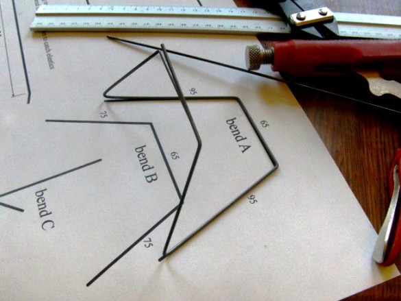
All the bends are shown on the plans. 'bend A'…
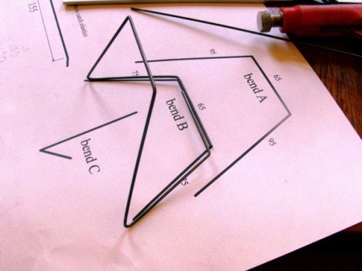
'bend B'…
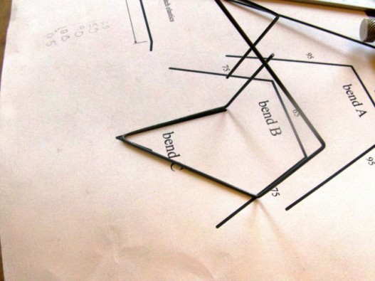
…and 'bend C'. You can make the frame from a single long wire, or break it up into smaller sections. I chose a single long wire.
Here's a test fit with the metal frame held together with zip–ties. Next stage is to join the overlapping portion with thread and CA glue.
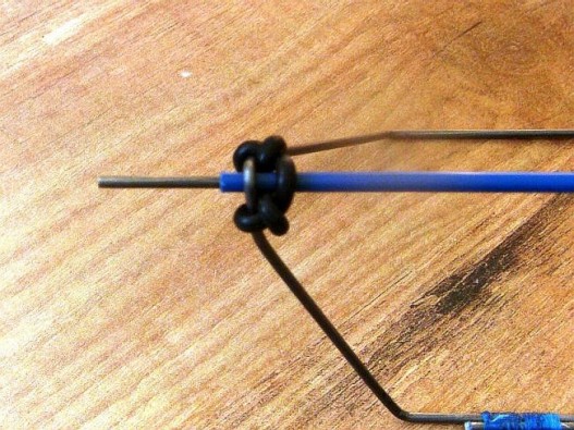
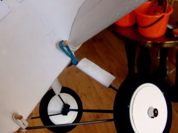
This undercarriage system uses rubber bands or prop rings to hold the axle in place and provide a little suspension. Not essential but I use a length of control rod snake to make a sleeve to cover most of the axle. The wheel can't go over the sleeve, so this helps to keep the wheel from rubbing against the suspension rubber. A washer would work as well. Note that the last 15mm of that bottom corner of the frame has been bent to make it near–enough vertical. This stops the 'pointy' end of the frame digging into the side of the wheel. A lesson I learned from 'chewing–up' the insides of my AVRO wheels.
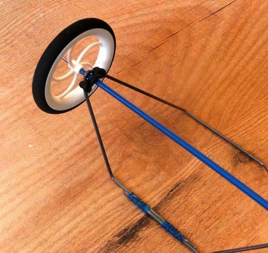
Complete frame, axle and wheel assembly.
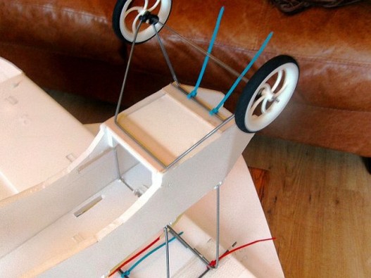
Once the skewers are fitted, elastics hold the undercarriage in place. This system worked well on my AVRO 539B. It may not be the neatest solution, but it's durable and forgiving if the plane has a rough landing. Previously when I've used a 'hard' fixing, I've ended up damaging the fuselage. A word of caution, this is not a battery tray. The skewer mount at the front is not strong enough to carry the weight of a heavy battery; the battery needs to be strapped to the power pod.
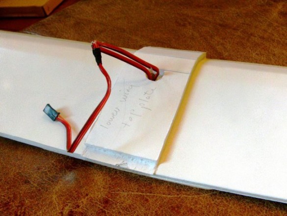
This picture shows how removing the front skewer allows the undercarriage mount to swing clear to fit the battery. Let's get that cabane assembly made and mounted.
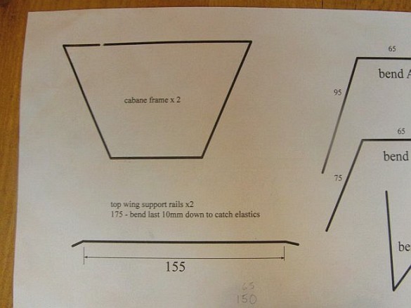
There's bending guides for the cabane frames in the plans. The two front frames are made up as shown in this picture, with no overlap. The third frame is identical in shape, but the wires at the top have a good overlap so they can be joined.
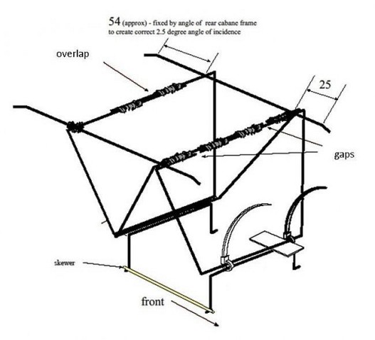
There's a 'neat' space–saving way to join the two front frames by placing the wires together with the gaps on either side. It's shown here, and on the assembly sketch in the plans.
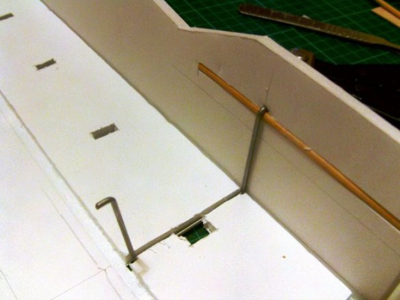
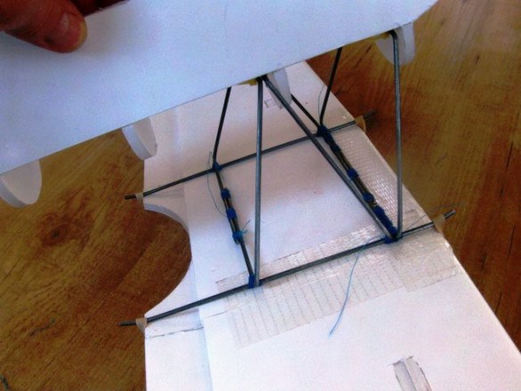
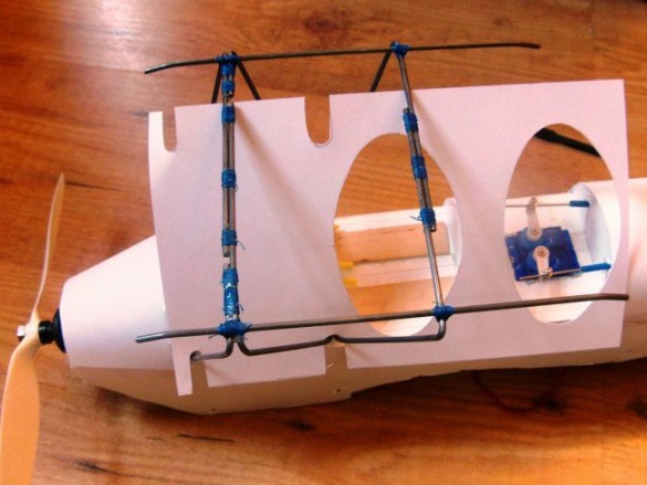
Bend up your three cabane frame wires and the two top wing support rails, and then fit the frames to the fuselage.
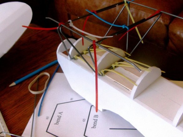
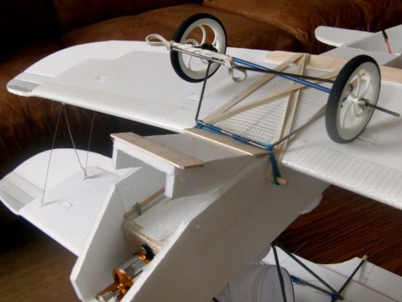
Here's the dry assembly. As well as holding the frame to the fuselage, zip ties are great for holding it all together. Once the frames are all sitting symmetrically side–to–side, the 8 zip–ties connecting the frame to the fuselage can be tightened reasonable firmly. See how the bottom of the frames rest against the tongue depressors. This helps spread any downward pressure into the fuselage, and stops the foam deck being crushed or deformed. The upward movement is resisted by the hidden cabane mounts, which connect into the fuselage sides.
Once you're completely happy with the shape and symmetry of the frame you can start to join it all together. Get those bottom zip ties nice and tight and then snip off the ends to make the next stage easier. Thread and CA is a laborious method, but it does get the job done. A little patience is all that's required. The thread does not need to be 'super tight' – once you add the CA it fills up all the gaps and bonds the threads together making them extra strong. Thin CA is best for this as it soaks into the threads, and if you use a kicker, wait a few seconds to allow the CA to be absorbed by the thread before setting the glue. Join the front pair of struts first. You can see how that 'neat' staggered join works, minimising the bulk of the join. As you add the thread joins, you can snip–off any zip–ties the join replaces. After these first four groupings of thread and CA I later added another four, two in the middle and then one more on each of the short legs.
Check the back frame against the front pair for a reasonable fit before binding it up. Here you can see the simple overlap of the top wires held in place by a single zip–tie. This is not rocket science, and not precision engineering. As long as it's reasonably neat, it will look fine on the finished model. I could set–up the angle of the top mounting rail using a full–size copy of the cabane geometry drawing and positioning it flush with the top of the box fuselage, but I think seeing the wings in place will help, so let's move away from the fuselage and get those wings built.
The top wing is made from 'handed' parts. One side includes the 'flat' wing centre. There are two dihedral 'turns' on the wing, which sit either side of the centre section. I aligned and taped the two wing sides together before making my leading edge bevel cuts and the shallow cuts and scores along the wing camber fold lines. My folded spars never come out as reliably as the laser–cut kits do, so I don't cut the tab locating holes in the wing until I have the spar assembled. Equally, I tend to cut one side of the spar profile, then fold the spar halves over and use my first cuts as a guide to cutting the second side. That way there's no problem of a mismatch if it doesn't fold just right. Not shown in the build sequence, but I actually have a 2.3mm piano wire reinforcing element spanning the centre 300mm of spar. This is shaped to the correct dihedral and sandwiched between the spar sides. I cut a slot in the centre of the spar on one side, just the same way as I embedded the skewer for the cabane mounts, and then glue the wire into the slot before folding and gluing the spar halves together. By all accounts, the wing doesn't need it, but my planes tend to be heavier than the dollar tree ones, so I like to be sure. The wire also helps maintain the dihedral angle and stops the spar from deforming during the build process. To stop the 'cold' metal setting the hot glue too quickly, I sit the wire in my kitchen oven for a few minutes at its lowest setting (40 degrees C). Not so hot I can't pick it up, but warm enough that the glue stays soft while the wire is bedding–in to its slot.
The joining tape is still in place, keeping the wing sides in alignment, so fold the entire wing, pressing it into shape and establish a constant profile along its full span.
Now cut through the tape holding the top surface of the wing panels together, just as far as the leading edge. And then on the other side of the centre panel cut through the foam on the top of the wing, again, only as far as the leading edge. This frees the centre section, ready to be folded into shape.
Score and introduce a fold at the edge of the centre panel, ready to make the dihedral.
Holes cut for the strut mounts – just big enough to slide the arm of a '9gram servo' through.
A careful dry fit of the spar gives me the final positions of the tab cut–outs on the bottom of the wing.
Same again for the other side.
After cutting out the tab holes for the spar, it can sit loosely located in both sides. This puts the centre section of the spar in the correct position, and it can now be glued in place. After the spar is set, slightly flatten the trailing edge of the bottom panel to increase the glue contact area before folding the centre section over and gluing it down. I only glued the leading edge fold, the top of the spar, and the trailing edge join. I didn't bother with gluing all the curve folds, and I've hung the back edge off the table as I pressed it into place to allow for any slight under–camber.
With the centre section set, it's time to make–up the right wing panel. Before working on the right wing section I lifted the left edge of the centre section with an off–cut of foam to allow the dihedral to form. Note the left wing section is still hanging on its taped join. Be aware this is vulnerable; you don't want it tearing off and messing–up all your careful alignment work. Once you're happy that the positioning of your off–cut is creating the correct dihedral angle (spar sitting flush along the top of the wing), lift the wing and run glue under the spar. Now set the wing down. Make sure the off–cut is back in the same place to form the dihedral and press down on the spar as it sets.
Now you want to fit the wing top panel. As it comes over you need to trim away material to get a flush fit. Do this bit–by–bit, gently laying the wing panel over the centre section and marking material to be removed.
Keep marking and trimming for a good fit. This is not a constant–width cut. It is widest at the fattest part of the wing and tapers away to nothing at the leading and trailing edges.
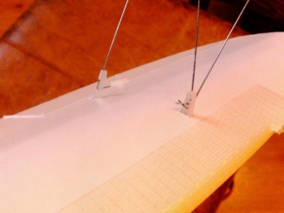
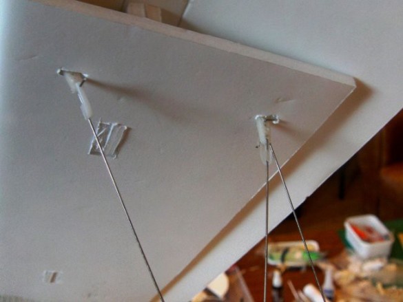
Before closing the wing you need to install the interplane strut mounts. Angle the front mount backwards and the back mount goes straight up and down.
Here they are, glued down from the inside. Do a test–closure of the wing and see how much the back mount interferes with the top panel. You will most–likely need to dent or even trim the top panel to get a good flush fit. Remember to put that 'dihedral' packing–piece back under the centre section before closing the wing over. Also you need to hang the projecting interplane mounts off the edge of your work surface to allow the bottom panel to sit flush with the table. It's a bit fiddly, but not impossible.
With the right side done – it's time to move to the left. This should still be aligned and ready to go with the tape still in place. As you prepare to glue the spar down, remember to run glue into the open join between the wing and the centre section. Using the same off–cut spacer under the centre section as you did before, hold everything firm to help the spar set at the correct dihedral angle. Once the spar is set, follow the same mark, trim and fit procedure to get the top panel to fold over. Fit your interplane strut mounts and then glue down the top panel. Carefully push glue into the two top joins and 'smear' finish them; finally add tape over the joins to finish the wing assembly.
I cut and shaped short sections of tongue depressor to reinforce the back edge of the wing for the elastics.
I 'cheated' with the bottom wing and didn't bother with a centre flat section. The wing assembly is much the same as before. Join the two symmetrical wing halves with tape before cutting the leading edge bevels and the shallow cuts and scoring of the folds for the curve. Now dry–form the whole wing to get an even shape across its span. Now cut the tape along the top of the wing so you can make the wing up one side at a time. Start left or right, it doesn't matter. Here I started on the left. I left the ailerons intact – they're already marked on and I'll cut them out later. First I made sure the dihedral turn on my spar was sitting dead centre and then cut the tab locating holes on both sides of the wing. Then I glued the spar in place on one side.
Fit your interplane strut mounts in the top of the wing, slightly angling both towards the centre of the wing. Install the servo at the end of the spar and position the servo wire alongside the spar, adding an extension or Y–harness as needed. Now you can glue down the first top panel. There's no problem with the strut mounts hanging out from under the wing, but still let the trailing edge of the wing hang over the edge of your table to let any under–camber form as the glue sets. With the first wing–half assembled, notch a little hole for the servo wire extension/Y–harness and lead it clear. Use a spacer to raise the completed wing half and establish the dihedral with the loose end of the spar sitting snugly in place on the bottom wing plate. Once you have a set–up that is stable and easily found again, run glue into the centre join and under the spar. Carefully re–position your dihedral spacer, and press down on the spar to let the dihedral set correctly.
Install your strut mounts and servo and then repeat the bit–by–bit procedure to get the second wing top fitting flush against the first.
Once you have a good fit, feed/join your servo wires and glue down the second wing half.
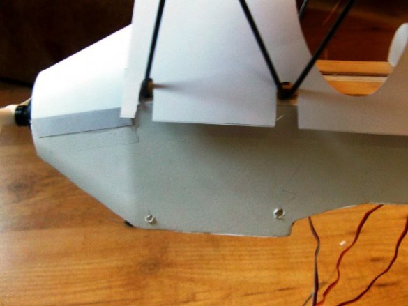
Now fit the lower wing top plate, making sure it is square and central when it sets.
I glued–on a tongue depressor to reinforce where the elastics go over the back of the wing.
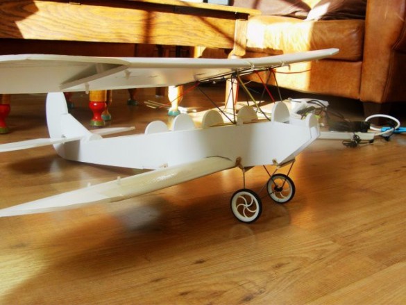
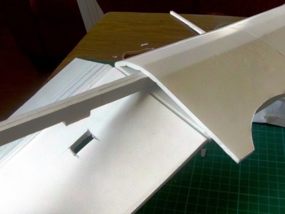
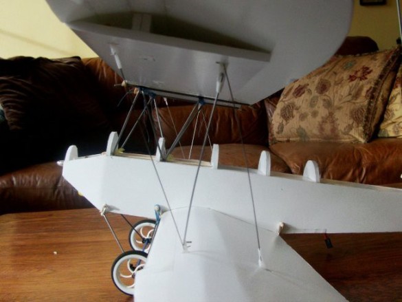
Now I have the two wings I can get an idea of how it's coming together. I've still to adjust the position of the rear cabane frame to set the angle of incidence of the top wing, and I need to make a few little adjustments to the cut–out in the fuselage for the bottom wing, but it's looking good so far.
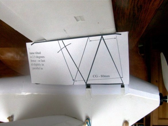
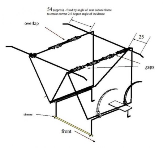
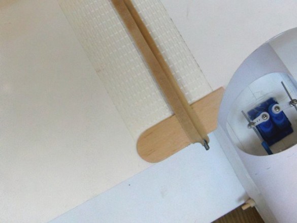
I didn't get a picture at the time, but here's my full–size copy of the cabane geometry drawing positioned flush with the top of the box fuselage. You can rotate and position the rear strut to get the correct angle of incidence before binding the mounting rails in place. I had a little rethink about my initial CG and the angle of incidence, so ignore the figures in this photo, they'll be right on the amended drawing.
All bound and fixed, but even at this stage there's plenty of 'wiggle room' regarding positioning of the wing. It can be moved side to side, forward and back and even rotated slightly if your cabane assembly is a little off.
Once you are happy with the wing alignment, add some centring pieces to the top wing to help position it on the cabane assembly. I've shown the wing out of its mount, but you would add these corners while the wing is in place. Now every time it goes back on, it will be pretty close to where it should be. These will deform with hard use, but they can always be replaced or repaired.
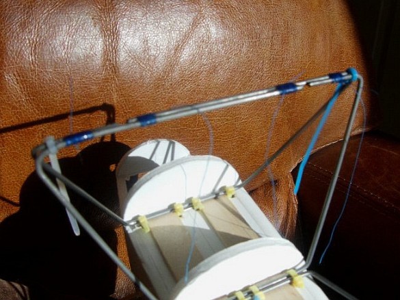
The interplane struts are fiddly and take a little patience. After aligning the top and bottom wings against the fuselage, I made–up the centre strut on each side and worked from there, adding the rear pairs and then the front pairs. These are really only there to help maintain the wings' alignment in flight, so a little flex here and there won't matter. Don't make them tight, as this will just change the dihedral on both wings, making the bottom dihedral sharper, and the top dihedral flatter.
The struts attach using modified Z–bends and right angle bends with swing–in keepers. It would get a bit crowded around the mounts it you used swing–in keepers at both ends. On the right you can see two modified Z–bends 'happily' sharing the mount.
There's a good sequence to attaching the interplane strut wires, which only has a swing–in keeper sharing the mount with a modified z–bend the one time. This is shown on the right here. Make sure the modified z–bend is well above the mounting point of the swing–in keeper.
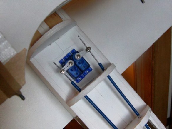
Based on the CG I calculated, and 'loose' component testing, I found I needed the weight kept forward, so I fitted my rudder and elevator servos in the rear cockpit space with snakes running to the rear. The tubes from cotton–buds are a good fit for this size of wire and you could use them at the tail and straws for the rest of the run. This space is not accessible once the turtle–deck is on, so you need to think it through and have the wires and/or snakes in place before you close the deck. The important thing is to eliminate any chance of the wire bending when the servo is 'pushing'.
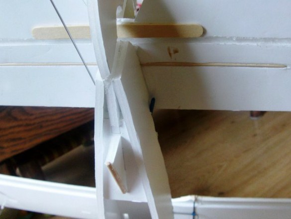
I 'filed' a hole into the foam with the side of a drill bit to bring the snakes out just under the horizontal stabiliser. A small, round rat's tail file would also be good for this job. Because of the need to pass through glue, just poking a skewer through will be quite hard. Glue the end of the snake in place to keep that little corner of the tail–to–fuselage join strong.
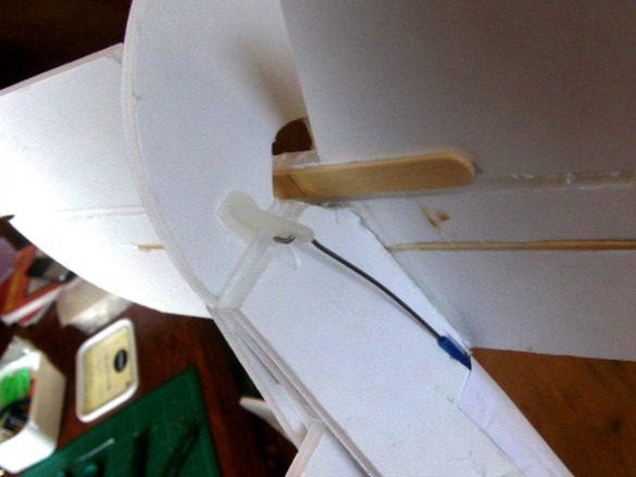
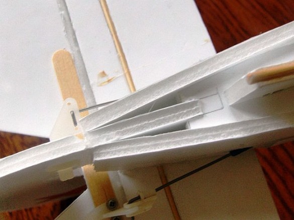
Here's the rudder connected–up.
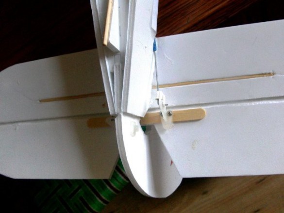
…and the elevator. Control horn glued and screwed in place! Belts and braces… Probably it would have made more sense to cut the bevel on the other side and put the lollipop stick on the top. OR, you could take the control rod out through the turtle deck above the horizontal stabiliser. Whichever way you do it, you'll see either the lollipop stick or the control horn on the top of the horizontal stabiliser.
Not much more to do. Here's the aileron cut free, the hinge bevelled and reinforced with hot glue, and the control horn connected up to the servo. Again I forgot to cut the bevel on the other side to make more space for my control horn. Home–made control horns can be a better fit in this situation.
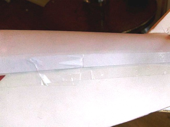
The turtle–decks are poster paper, taped and glued using the familiar Flite Test system. Start at the tail and work forward. I was a bit quick and missed the photographs of this stage, but here's the template in position, showing how the back section centres around the vertical stabiliser.
Because the turtle deck cover passes around a curve, I snipped little nicks in the edge of the paper to get a better fit. Normally I glue these overlaps down, which might have made the joins neater, but I wanted to use the 'Flite Test' clear tape system that folks are familiar with. Then I saw Josh gluing down the turtle–decks on the FT minis using hot glue, so I should have just stuck to my original method. Josh added a neat twist though, instead of starting at the side, he started at the top of the former which seemed to make it a bit simpler. Have a look at the FT mini's build video and see what you think will work best!
Next there's a short section behind the second cockpit, this sits on a straight–sided section of the fuselage, so is simpler to fit. If you're going to mount a machine gun on there, stick another little bridging support between the curved formers to support the mount.
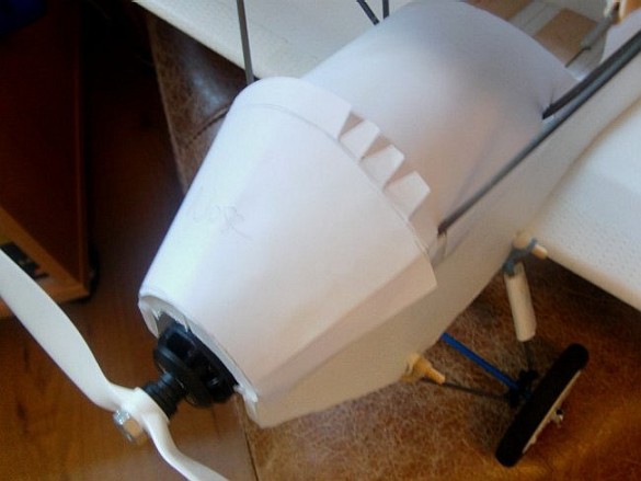
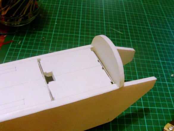
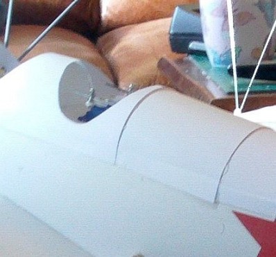
A later picture, so the cockpit section is already in place, but the next step is to fit the nose. Press the nose piece into place to find where the large former finishes and mark this line on the paper. Snip out little triangles up to that line as shown (but all the way round). This allows the paper to fold over the former and lie flat. You might want to put this off until the very end of the build in case you want to add nose weight on top of the pod to get the CG sorted.
With the nose section in place, start fitting the cockpit and cabane section. This needs cut–outs to go around the cabane wires.
Just keep removing material until the turtle deck sits in place, in full contact with the formers when pulled tight. Glue or glue and tape into place.
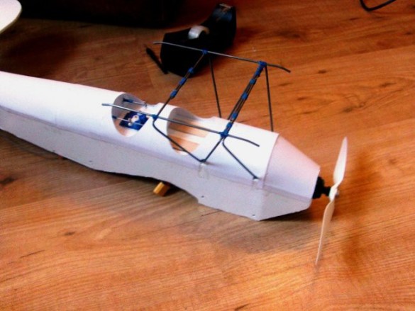
Here are all the turtle decks fitted. I've included a template for the windscreens if you want to add those. A little 'padded' cockpit edge made from split and stripped round electrical wire or insulating sleeve would be another simple feature to add a bit more character.
The wheel spokes were filled–in using my olde–style wheels for olde–style planes method, and I added the teardrop fairings on the rear undercarriage wires. These wrapped around the springs/shock absorbers on the real plane. A 'wing type' nose bevel in the centre of the 40 mm face of a 30 x 40 mm blank will make a rounded leading edge, and a deep bevel on each outer edge will wrap around the wire to make the elongated teardrop shape. I stuck these on with foam safe CA, and to finish I wrapped and pinched clear tape around the trailing edge to sharpen it up.
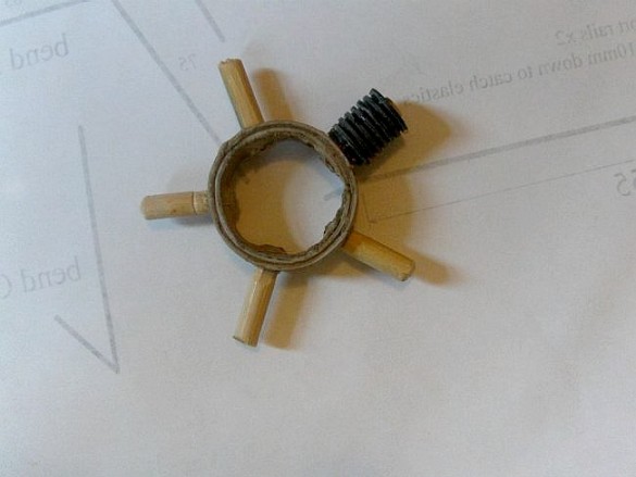
The only other addition to the plane is the dummy motor. Each engine cylinder is made–up from a stack of two different sizes of black nylon washers glued to a short piece of dowel. The dowels are first glued into a thick cardboard ring.
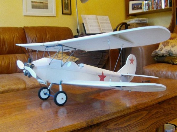
I printed the Russian stars onto self–adhesive parcel labels and cut them out and stuck them on. By a lucky coincidence, this everything white finish is the winter colours for this and many other Soviet planes during WW2. I've seen a version of this plane with skis fitted to the existing undercarriage frame, and that might be a fun mod for winter flying. There's also a float plane version, and if someone had the patience to waterproof everything, this would make a great seaplane. On mine, everything has been sprayed with mat varnish, which will keep off most of the dew, damp and fog I encounter.
The dummy motor still needs a final coat of paint, but it definitely adds to the look of the plane. Built 'carefully' in lighter foam board, I can see this coming out at around 800grams with a 2000mah LiPo. Even at just over 1Kg my plane still manages to fly very sedately, so at lower weights it will perform even better, and fly for longer. There are no slow–motion effects in the maiden flight video, and the winds were about 5–6mph, so that should give you a good idea of the plane's potential. For the maiden I started with a few trim 'clicks' of right rudder, and a few 'clicks' of right roll on the ailerons. My elevator was flat. I also set–up a reasonably gentle aileron–rudder mix. I started in low rates, everything on 50%. Initial full–range motion on the ailerons and elevator was 40mm (20 up, 20 down). The rudder has a full range of 50mm.
First launch was with too much power and the plane climbed aggressively and had looped over my head before I cut the power and got it safely down. I put in a whole load of down elevator, moved my battery forward a bit and reduced power to try again… that's the first flight you see in the maiden. As I got the plane under control it was clear the rudder wasn't doing much, the ailerons were OK but a bit 'anaemic', and the elevator was too aggressive. But it was flying so I kept it in the air to trim it out and get the feel for it. It still wanted to climb, so I kept feeding–in down elevator trim until I ran out of range. The rest of the flight was Ok, but I had to manage the elevator constantly with a little down elevator to maintain level flight. Under power, the plane wanted to climb even more, so I reckoned I needed a bit more down thrust on the motor. UPDATE - A better modification would be to reduce the Angle of Incidence - currently 2.5 degrees (which is accurate for the 3 view plans I sourced on the internet), but it could probably probably be reduced to 1.5 degrees, reducing the need for negative inputs like steep motor thrust angles and a lot of 'down elevator'.
I landed when the battery alarm sounded and examined the transmitter. I seemed to have removed all the right trim on the ailerons, but the rudder still had a few clicks of right on it. I went into the sub–trim menu and adjusted my elevator into an initial down position, which allowed me to get my trim range centred. I upped the range of throw of my rudder and ailerons in the dual rates to 65% for the ailerons and 80% for the rudder. I dropped the low rate on the elevator to 40% (I also set the elevator high rate to 75%). I moved the battery forward a little more and set the plane off again. That's the next launch in the maiden video (1:17) – the plane just floats out. There was a little elevator trimming, but once that was done the plane was pretty steady. The rudder still wouldn't do much until I used a touch of aileron to bring the wing over (especially on right turns, suggesting the need for a little more right thrust on the motor) but it did not detract from the experience, which quickly became very enjoyable. I tried some loops, which were easily accomplished and uncomplicated with no bad tendencies as it came out of the loop.
The CG on this flight was 84mm back from the leading edge of the top wing.
Time in the air from launch to battery alarm for my 1500mah LiPo was 12.5 minutes of mixed (but mostly sedate) flying. Which I felt was pretty good. This improved by almost a minute with the after–maiden modifications I mention in the tuning and flight testing video. Any omissions or glaring errors in my history, plans or build sequence please let me know. Any questions, please ask. Please only attempt this build if you are confident with building other more complex foam board models like the Flite Test spitfire or cruiser.