Wingspan – 760 mm 30 inches.
Length – 635 mm 25 inches.
AUW – 590 grams 21 ozs with a 1000mah LiPo.
Drive - FC 28–22 1200kv motor with an 8 x 4.5 prop.
Plans – PDF file. (Can be printed on A1 foam board.) Tribewt 2
This plane was built as a demonstration plane for the 'Build a Tribewt' article published on the Flite Test website. It was intended to highlight the versatility of the Flite Test build method.
The planes in the 'Tribewt' series are all derivatives of the Flite Test Baby Blender – using most of the basic component and fuselage dimensions. By altering profiles and turtle deck heights etc. different types of planes can be modelled.
Initially I stuck with the Baby Blender wing design, which allowed a 1 sheet = 1 plane build, but as more 'realistic' wing designs were demonstrated on the Flite Test website it was obvious these would complement and enhance the builds, as in the last design – the GeeBee Sportster Tribewt.
Preparing the pieces.
Print up your plans as tiles and stitch them together to get templates for all the components. If you're lucky and can get A1 foam board to a commercial printers with a flatbed printer, they can print the plans directly to foam board on the A1sheet.
The Fuselage.
Cut–out your box–fuselage template from the plans, mark out your foam board and cut it out. Leave a little extra material around the wing cut–outs. Even from the same plans, not everyone's wings turn out the same. You can trim to fit later.
You'll need to 'ease' a front and back bend – scoring the paper first. Then fold up and glue the 'A' Type bend.
Crease and bend your fuselage stiffener pad.
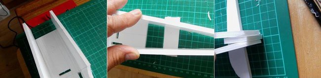
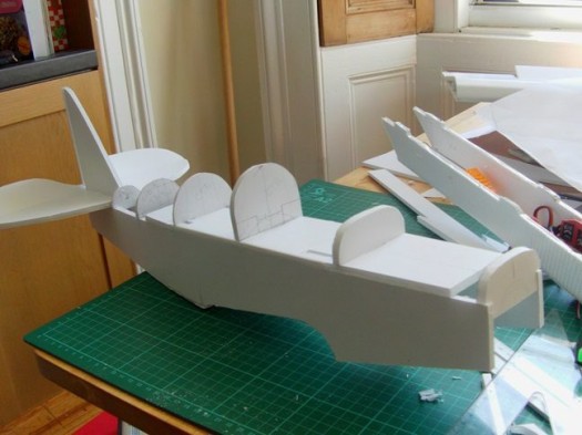
Using the grid on the cutting mat I lined up the fuselage components. I have a centreline on the underside of the pod carrier to help with this. Note the little spacing pads under the tail section to stop the fuselage tipping. I've placed an extra layer of foam board in the middle at the back where the rudder keel will go – and the middle of this is lined–up on the correct grid line.
This is actually from another build, but you can see how I use the wing centring plate to set the width of the fuselage as I fit the fuselage stiffener that goes just behind the wing.
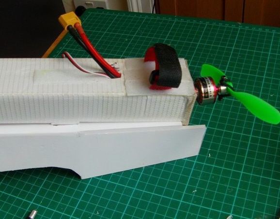
Now fit the swappable pod – test fit and align the locating lugs. The BB build advice is to make these fitting slots short until you can fit them to your own pod.
Here's the pod in place.
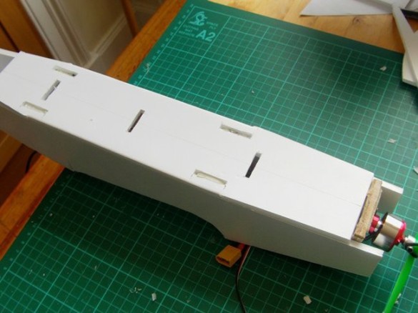
Sort out the position of the skewer mounts.
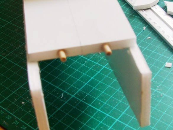
Fit them!
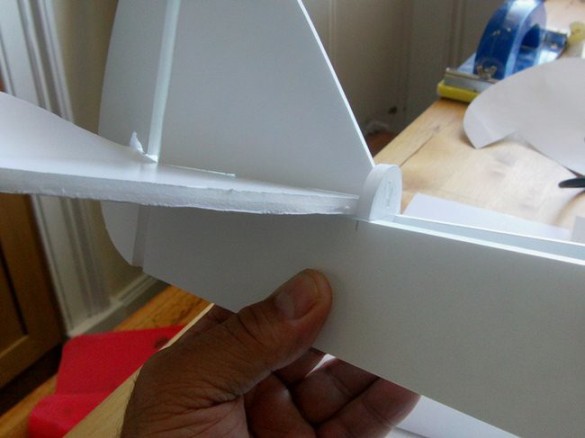
Here's my vertical stabiliser. Prepare this and the horizontal stabiliser as the BB build, adding hinges etc.
Do a dry fit and make sure you get adequate movement from both control surfaces on all combinations of movement.
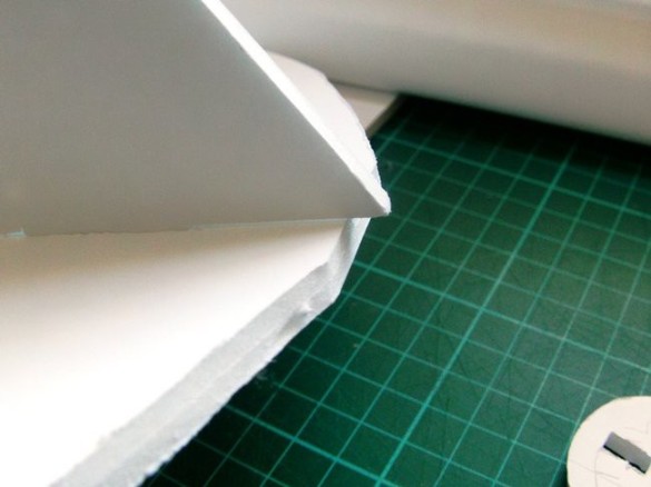
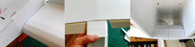
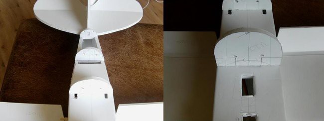
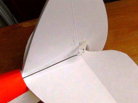
The vertical stabiliser projects slightly over the horizontal stabiliser…
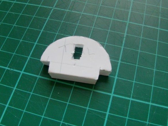
…so it locates in this turtle deck former.
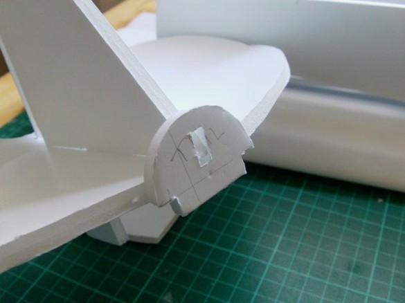
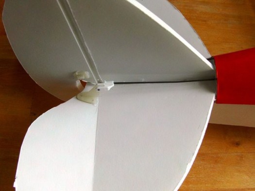
See how it works.
This helps centre the tail assembly.
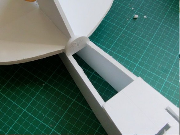
First join the vertical stabiliser to the horizontal stabiliser making sure they are square, and then glue the tail assembly to the fuselage. The plans show locating and centring lugs to help line–up the tail with the fuselage. If you're confident about getting everything square without them, they can be omitted.
The Wing.
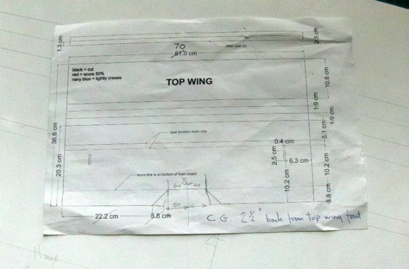
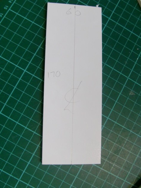
The Tribewts 1 & 2 use the Baby Blender top wing folding detail, but this is extended to 70cm wide (or you can take it to the full width of the A1 sheet – 840mm – this is explained in each of the plans). Ignore that CG, that's for the original Baby Blender.
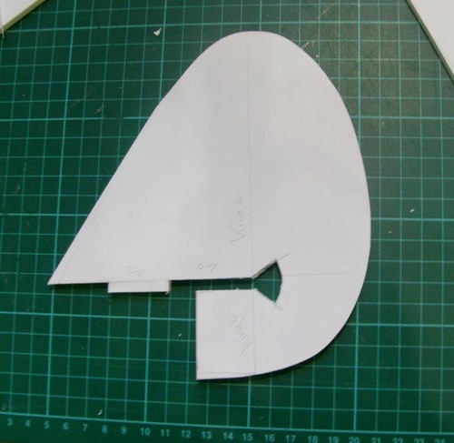
Use the plan template to mark out your wing.
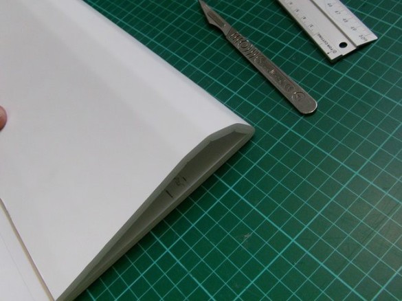
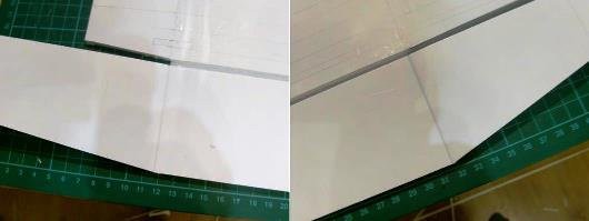
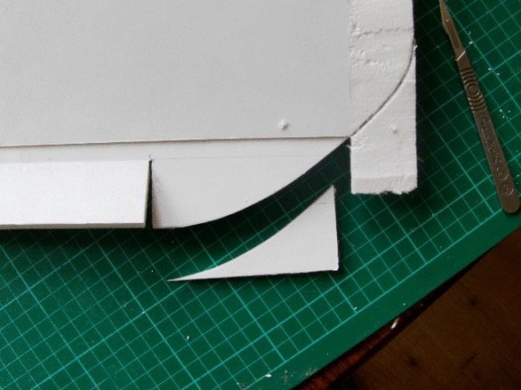
If this is unfamiliar, refer to the Flite Test build videos of the Baby Blender to see how to prepare the wing. In the picture above I've already made the half–depth cut and bevels for the leading edge fold and scored the fold lines that give the wing its shape. But don't glue the leading edge yet! This plane has dihedral, so you'll need to split the TOP of the wing down the centreline.
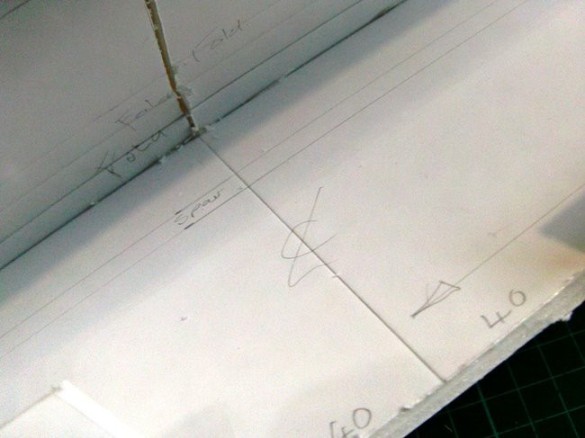
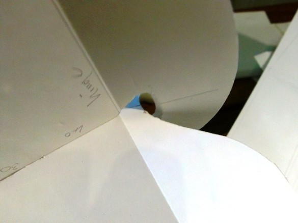
On the BOTTOM of the wing crease the paper down the centreline and gently bend it to form a shallow dihedral.
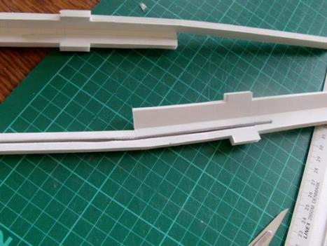
If you want, the dihedral spar can be reinforced with a 300mm length of 2.3 mm piano wire. I reckon as thin as 2mm would work, but I liked the 'stiffness' of the 2.3 wire. Here's typical detail from another build.
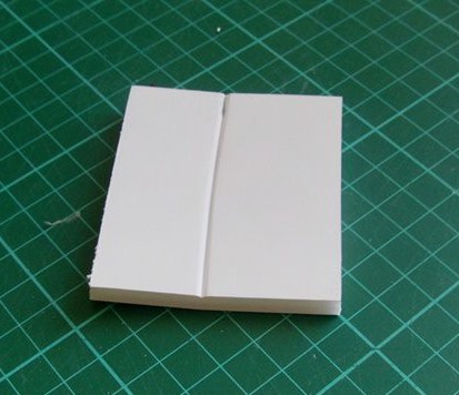
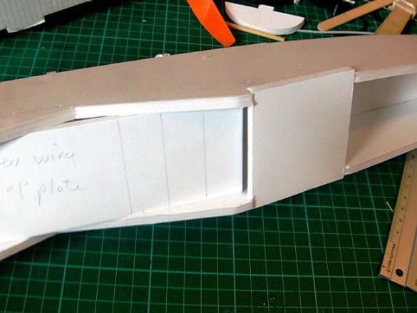
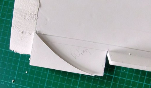
Here is the wing centring pad.
The fold points that make up the curve of the wing are given in the plans. Make half depth cuts across the pad and spring the cuts open. Glue the pad onto the top of the wing making sure it lines up with the centre of the wing (front and back). This pad centres the wing to the fuselage and also adds strength to the join – so it's important to get a good bond, and to get it in the right place.
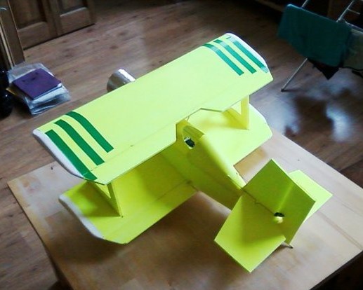
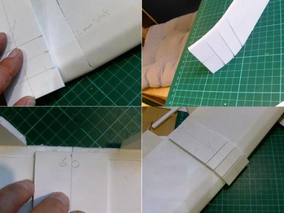
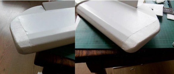
In my original build I added foam wingtips. It's your choice, but as well as extending the wingspan this gave a more finished appearance to the wing.
I was able to find foam that would add another 4cm each side, increasing the wingspan to 78cm. I used a fairly dense polystyrene which doesn't pick apart too easily.
You only need enough to cover the thicker part of the wing. Glue it on with hot glue – pressing firmly until the glue sets to make sure of a good fit. The glue takes a little longer to cool and set as the polystyrene traps some of the heat.
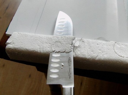
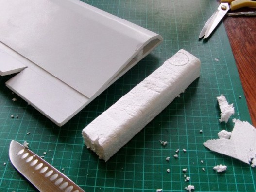
Once the glue is set pare the foam down using a very sharp kitchen knife.
Lots of thin cuts, using a slight sawing action! With the kitchen knife I find I can rest a good portion of the blade on the paper, which helps pick up the shape of the wing and extend it onto the foam for the last few cuts.
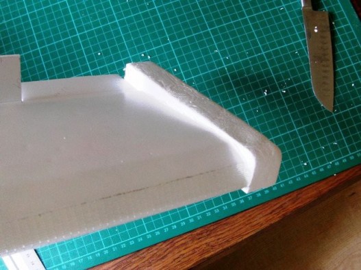
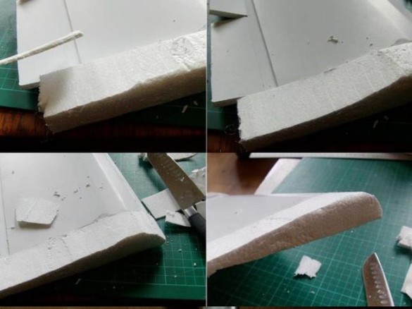
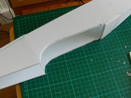
Add some shape to the trailing edge of the wing. Whatever shape you choose it's best to take the cut through this step–point in the wing, just where the foam board goes to double thickness.
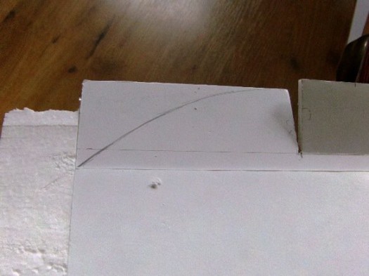
Sketch–on a curve and extend your design onto the foam wingtip.
Use a craft knife and a sawing action in the foam to trim off the excess. If you can keep the off–cuts in one piece…
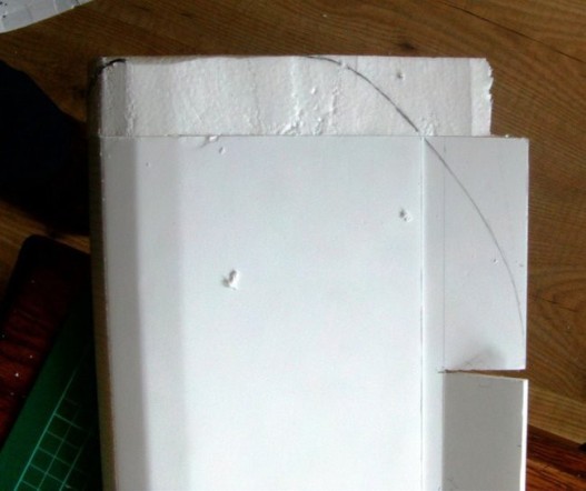
…you can use them as templates to mark the curve on the other end of the wing.
After some gentle paring with the kitchen knife to remove the sharper corners, the foam can be sanded – use old finer–grit paper that has lost its 'catchiness' and go very gently. It might take longer to sand but you'll avoid tearing off chunks. You can now paint the foam with slightly watered PVA glue to strengthen it. This coating will also stop the foam melting if you decide to spray paint the model.
Now you can make the final adjustments to the wing cut–outs in the fuselage.
Test fit and marvel at your precision!
The Turtle Deck.
Here's a quick test–fit to see how it all looks.
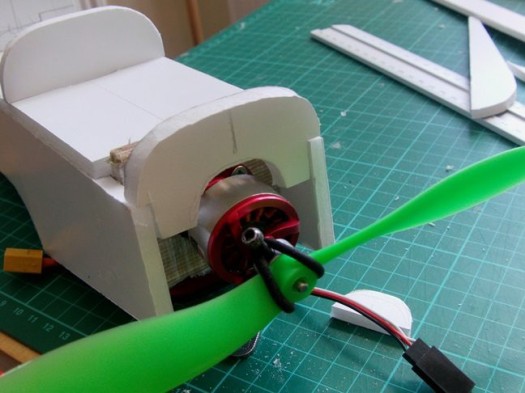
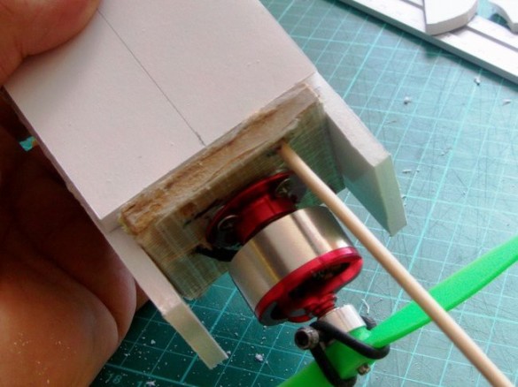
You may need to adjust the motor cut–out if your motor is larger. Make sure lots of air can get in and around the motor.
Use the templates to cut out your turtle deck covers.
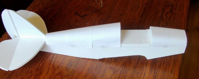
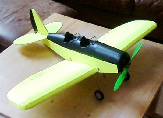
Here's a test fit of the nose, headrest and tapering tail.
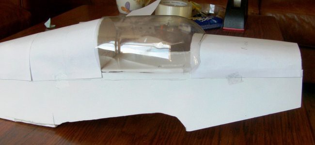
At this stage you might want to get a bit creative – you might even omit the headrest former and make up a longer cockpit canopy?
Before fitting the turtle deck covers test fit the servos and control rods. I positioned the servos down the centreline in the middle of my cockpit. Then worked out where the control rods would go. It's much easier to create a series of holes to feed the control rods through without the turtle deck in place.
Here it is with the plan turtle decks glued in place. I use card for longevity, but you can use poster paper for a lighter build.
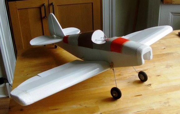
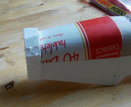
The Nose.
This could be left as–is or you can add some detail.
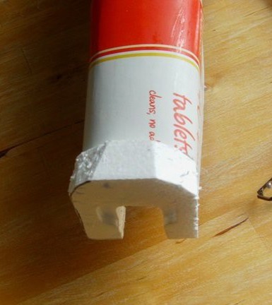
I was lucky to find some foam with a slot in it and a bit of preformed shaping – I cut this to an oversize outline and glued it on with hot glue.
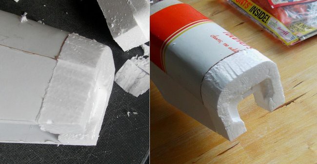
Pare this down with a sharp knife, following the outline of the nose…
…then sand it carefully.
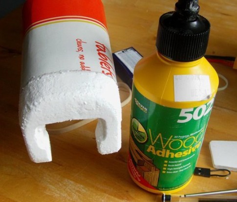
Finish the foam with a couple of coats of slightly dilute PVA glue.
Fittings.
All the fittings are pure BB.
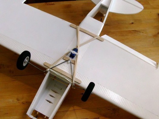
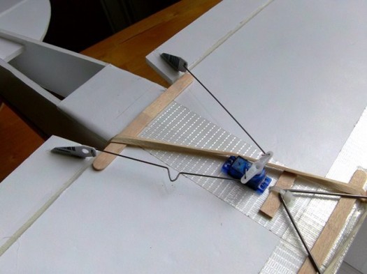
Here's the lollypop sticks on the wing to take the pressure from the wing elastics, centre aileron servo, single attachment for the undercarriage, and skewers in the fuselage for the wing elastics. On this plane the front skewer needs to be removable to fit the pod so don't glue it in place. Note the use of packing tape on the wing leading edges and other places I think it might be useful.
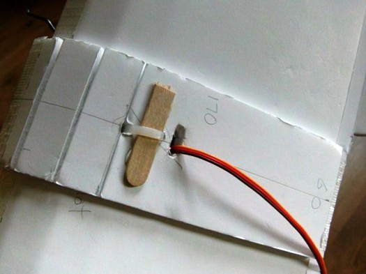
The top of the wing zip–tie holding the undercarriage in place with lollypop stick reinforcement. Feed hole cut for the servo wire.
Rudder control horn. I like these swing–in fittings for locating the control rod. Not too obvious here, but the control rod has a slight offset bent into it to take it from the back of the fuselage to the end of the horn. This removes any binding as the control rod passes through the fuselage. The wire bends up (slightly) and at the point where it lines–up horizontally with the control horn it is bent down (slightly) to 'straighten' the wire. Keep these bends shallow and no additional spring or unwanted movement will be added to the control rod.
Elevator control horn. Again you can just see a little bend in the control rod. I've still to fit two small screws through the horn, which will catch on the popsicle stick underneath and make everything super–secure.
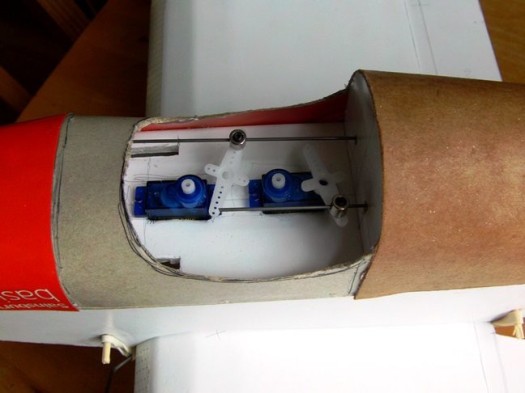
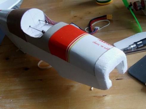
Here's the servos at the front. These aren't glued–in yet as I've still to paint the model. (Before painting stick a little bit of masking tape over the foam board to keep an area clear for hot gluing.) They can fit in–line like this or sit side–by–side; more recently I've just been fitting my servos side–by–side.
Aileron servo and horns. This is a simple as you can get it with bent wire adjustment on one side only, as adjusting one side affects both sides. Again nothing glued until after painting. The control horns are chopped–up credit/store/gift cards.
Finishing.
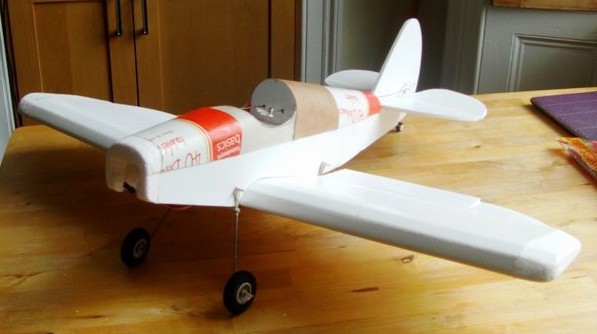
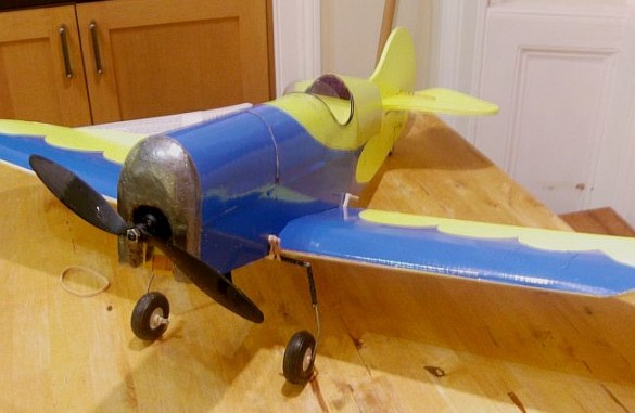
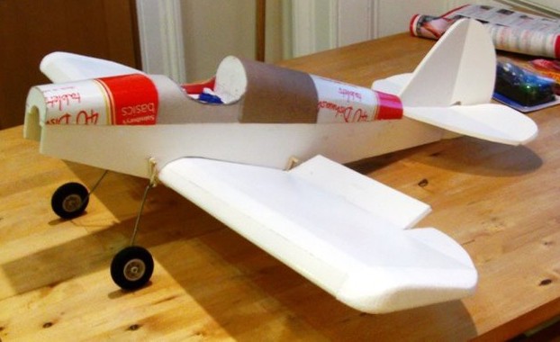
Final test assembly before painting.
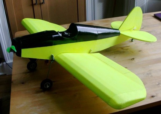
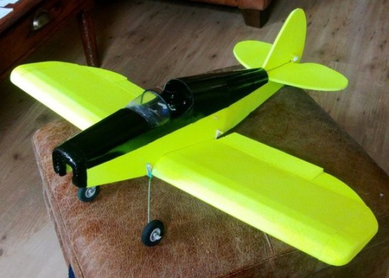
I do like this black and yellow paintjob. (Mostly because that's what I have sitting around.)
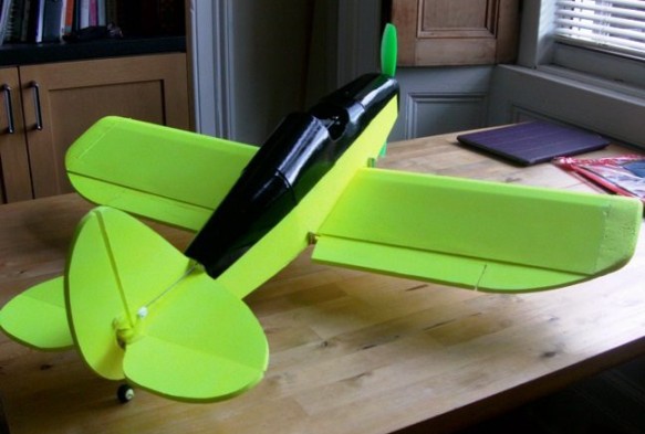
Here it is with a windscreen and a fake padded edge around the cockpit. I misted the windscreen with excessive applications of CA – but that would be authentic for flying in Scotland. :)